After comparing your battery voltage graph and SOC graph, there is a correlation.
As if there is a straight line curve 55.8V = 100%, 51.9V = 50% and 48.0V = 0%
You mention around 53% at 52.239v, right?
55.8V - 48.0V = 7.8V
7.8V | 100% SOC | 55.80V |
7.41 | 95 | 55.41 |
7.02 | 90 | 55.02 |
6.63 | 85 | 54.63 |
6.24 | 80 | 54.24 |
5.85 | 75 | 53.85 |
5.46 | 70 | 53.46 |
5.07 | 65 | 53.07 |
4.68 | 60 | 52.68 |
4.29 | 55 | 52.29 |
3.9 | 50 | 51.9 |
3.51 | 45 | 51.51 |
3.12 | 40 | 51.12 |
2.73 | 35 | 50.73 |
2.34 | 30 | 50.34 |
1.95 | 25 | 49.95 |
1.56 | 20 | 49.56 |
1.17 | 15 | 49.17 |
0.78 | 10 | 48.78 |
0.39 | 5 | 48.39 |
0 | 0 | 48 |
Hereby lies the problem.
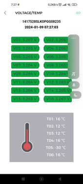
Lifepo4 battery will maintain flat voltage level of 3.2V or 3.3V between 10% - 90% = 3.2 x16 = 51.2V or 3.3 x 16 = 52.8V.
Only at the last 0%-10% where the voltage will fell from 3.0V to 2.5V steeply. Same for 90%-100% range where the voltage will suddenly rise steeply between 3.45V - 3.65V.
You really ought to request your dealer/manufacturer not to use voltage as SOC reference.......?
edit:
You sure the BMS is communicating with the Growatt inverter correctly? The more I take a look, the more I think there is no communication between the battery and growatt at all. Cause that pattern seems to be similar to Growatt "US2" mode where by a drop of 2volt resulted in steep SOC state.
Can you verify at Growatt display there is "LI" near the battery logo and percentage being shown there?