Hello,
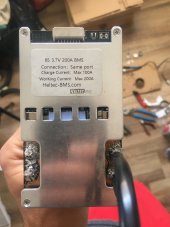
I have a heltec 200A BMS common port going on a 6S 5kw 21700 EV module as an off grid power wall build.
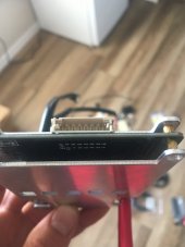
There is no spec sheet and a one page Chinese diagram included with this BMS.
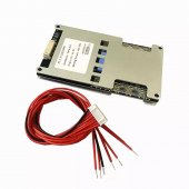
The guy who sold me the battery builds power walls for a living. He advised I solder/heat shrink all leads to the BMS harness, then connect the B- lead to battery negative terminal, then connect the harness with all the balance wires.
My confusion is that everything I’ve seen on YouTube and other write ups, barring my misunderstanding, says to connect the B- to battery negative BEFORE soldering the balance wires/sense leads SEQUENTIALLY. This makes sense in a way re internal circuitry, except it seems sketchy to be soldering live connections, and goes against all other electrical work I’ve ever done.
Can I just hook up the B- to battery negative and then plug in the harness with all balance leads connected? I’m paranoid about frying the thing.
Thank you very much!
I have a heltec 200A BMS common port going on a 6S 5kw 21700 EV module as an off grid power wall build.
There is no spec sheet and a one page Chinese diagram included with this BMS.
The guy who sold me the battery builds power walls for a living. He advised I solder/heat shrink all leads to the BMS harness, then connect the B- lead to battery negative terminal, then connect the harness with all the balance wires.
My confusion is that everything I’ve seen on YouTube and other write ups, barring my misunderstanding, says to connect the B- to battery negative BEFORE soldering the balance wires/sense leads SEQUENTIALLY. This makes sense in a way re internal circuitry, except it seems sketchy to be soldering live connections, and goes against all other electrical work I’ve ever done.
Can I just hook up the B- to battery negative and then plug in the harness with all balance leads connected? I’m paranoid about frying the thing.
Thank you very much!