2Big2B
Free Wheeler
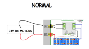
I have a application that uses 24vdc /100ah as motive power: My power wheelchairs. They are designed for 2x12v series lead acid batteries.
I have successfully been running with DYI LifeP04 battery packs each using an 100ah, 24v 8s Overkill BMS. The issue is that I lose power suddenly and intermittently. It seems related to power draw. I have no issues on straight battery though. I believe the BMS is seeing it as a short circuit and shuts down.
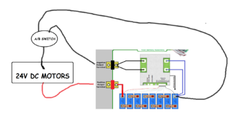
Assuming that, one solution, which Overkill Customer Support seems to agree with me on, is to install an A/B switch with one position for charging through the BMS and the other position for running direct from battery. It seems safe enough as long as I flip the switch as appropriate.
But what if I just bridge the negative output from both together instead of isolating them? Would that work without frying something the BMS, and would the LifeP04 battery cells remain balanced by the BMS?
I have successfully been running with DYI LifeP04 battery packs each using an 100ah, 24v 8s Overkill BMS. The issue is that I lose power suddenly and intermittently. It seems related to power draw. I have no issues on straight battery though. I believe the BMS is seeing it as a short circuit and shuts down.
Assuming that, one solution, which Overkill Customer Support seems to agree with me on, is to install an A/B switch with one position for charging through the BMS and the other position for running direct from battery. It seems safe enough as long as I flip the switch as appropriate.
But what if I just bridge the negative output from both together instead of isolating them? Would that work without frying something the BMS, and would the LifeP04 battery cells remain balanced by the BMS?