diy solar

diy solar

3x 100A BMS (problem with Multiplus discharge) or 1x 300A BMS?

DutchCookieMonster

New Member
Joined
Jan 6, 2022
Messages
27
Location
Lutjebroek, Holland
Hello,

On this moment I have
3x Overkill Solar BMS (16s 100A)
with 3x USB Module for BMS. Considered as SerialBattery(LLT/JBD) In CerboGX
I got the BMS visible in Cerbo by using the Louisvdw/dbus-serialbattery driver.
3 sets of 16 cells LifePo4 280Ah. Is 3x280Ah=840Ah total.
3x16 Grade A EV LF280K 6000 cycles lifepo4 3.2V 280Ah battery Jenny Wu Docan Technology (shenzhen)

The problem I have is that the Inverters (3x Multiplus 48/8000 (3Phase) stops wit discharge (Idle) between 45% an 55% of the battery capacity.
At the moment, there seems to be no immediate solution to it. (at least not on the Victron forum) Maybe one of you has experience with this?
It seems that something is not going well in terms of calculation in the multiplus with the 3x data of the BMS. But this I don't know for sure.

I was thinking of switching to 1 BMS of 300A in the hope of solving the problem.
What is a good quality BMS of 300A that can also communicate well with Louisvdw/dbus-serialbattery driver. and CerboGX

I'm looking for the same or higher quality BMS. I'd love to hear your advice (especially from those who also have a 3 phase multiplus 48/8000 system?) I would also like to hear why a certain BMS is better and also where they can be purchased. I live in the Netherlands and prefer to buy in a Dutch web shop, or worldwide webshop that can and may also deliver to the Netherlands. (at normal shipping costs)

Thank you in advance for thinking along.
vilage next to me
 
no i don't use them my self, i have a 12v system with 2 times daly 200ah.
what i have always read about the things is the relays are of a ifi quality but you can swap them out for a good quality


still i think your config can be better.
but maybe @sunshine_eggo can have a look at it

 
no i don't use them my self, i have a 12v system with 2 times daly 200ah.
what i have always read about the things is the relays are of a ifi quality but you can swap them out for a good quality


still i think your config can be better.
but maybe @sunshine_eggo can have a look at it

Which configuration settings could be improved?
Here I have the settings in a text overview.

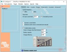
TAB: General
System frequency 50Hz
Shore current 25.0 A
Overruled by remote checked
Dynamic current limiter unchecked
External current sensor connected (see manual) unchecked
State of charge when Bulk finished 95.0 %
Battery capacity 840 Ah
Charge efficiency 0.95
TAB: Grid
Country / grid code standard Europe: EN50549-1:2019
AC input 1 Above selected gridcode plus LOM B (compliant)
TAB: European grid code settings
Use Aux1 as disable FeedIn signal checked
Maximum AC current for charge or feed in 100.0 %
Maximum generated apparant power 100.0 %
connect waiting time 60 s
connect power ramp 0.0 seconds
low frequency connect value 49.500 Hz
high frequency connect value 50.100 Hz
low voltage connect value 85.00 % Un
high voltage connect value 110.00 % Un
re-connect waiting time 60 s
re-connect power ramp 600.0 seconds
low frequency re-connect value 49.500 Hz
high frequency re-connect value 50.200 Hz
low voltage re-connect value 85.00 % Un
high voltage re-connect value 110.00 % Un
rise-in-voltage protection U> 110.00 % Un
under voltage stage 1 85.00 % Un
under voltage stage 1 delay 0.50 s
over voltage stage 1 115.00 % Un
over voltage stage 1 delay 0.50 s
under frequency stage 1 47.500 Hz
under frequency stage 1 delay 30.00 s
over frequency stage 1 52.700 Hz
over frequency stage 1 delay 30.00 s
under voltage stage 2 80.00 % Un
under voltage stage 2 delay 0.20 s
over voltage stage 2 120.00 % Un
over voltage stage 2 delay 0.20 s
under frequency stage 2 47.000 Hz
under frequency stage 2 delay 0.20 s
over frequency stage 2 53.000 Hz
over frequency stage 2 delay 0.20 s
P(f>) start frequency 50.200 Hz
P(f>) stop frequency 50.200 Hz
P(f>) start delay 0.00 s
P(f>) stop delay 30.00 s
P(f>) droop 5.00 %
P(f<) start frequency 49.800 Hz
P(f<) stop frequency 49.800 Hz
P(f<) start delay 0.00 s
P(f<) stop delay 30.00 s
P(f<) droop 5.00 %
P(U) response Not used
Reactive power regulation Use a fixed Cos Phi
Filter time for reactive power 3.3 s
Cos phi at point 1 1.00
Use lock-in/out unchecked
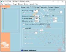
TAB: Inverter
PowerAssist unchecked
Inverter output voltage 230 V
Inverter DC shut-down voltage 37.20 V
Inverter DC restart voltage 43.60 V
Low DC alarm level 43.60 V
Do not restart after short-circuit (VDE 2510-2 safety) unchecked
enable AES unchecked
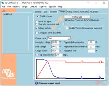
TAB: Charger
Enable charger checked
Weak AC input unchecked
Stop after excessive bulk unchecked
Lithium batteries checked
Disable VSense (for diagnostic purposes) unchecked
Configured for VE.Bus BMS unchecked
Charge curve Fixed
Absorption voltage 56.80 V
Float voltage 54.00 V
Charge current 110 A
Repeated absorption time 1.00 Hr
Repeated absorption interval 7.00 Days
Absorption time 1 Hr
Stop charger below 2.0 deg C
TAB: Virtual switch
TAB: Usage
Virtual switch usage Do not use VS
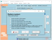
TAB: Assistants
TAB: Assistant Configuration
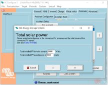
ESS (Energy Storage System) (size:1763)
*) System uses LiFePo4 with other type BMS
(This can be either a BMS connected via CAN bus or a BMS system in which the
batteries are protected from high/low cell voltages by external equipment.)
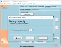
*) The battery capacity of the system is 840 Ah.
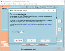
*) Sustain voltage 50.00 V.
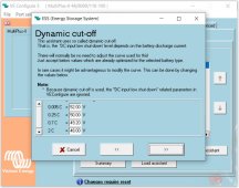
*) Cut off voltage for a discharge current of:
0.005 C= 52.00 V
0.25 C= 50.00 V
0.7 C= 49.20 V
2 C= 48.00 V
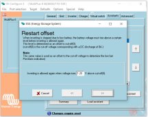
*) Inverting is allowed again when voltage rises 1.20 V above cut-off(0).
*) The solar converter will start reducing its output power at 50.20 Hz.
Output power will be reduced to minimum when the frequency is 52.70 Hz.
The converter will disconnect when the frequency is higher than 53.00 Hz.
*) Total installed PV inverter power is 8000 Watts.
Total installed PV panel power is 8000 Watts.
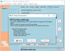
*) Relevant VEConfigure settings:
- Battery capacity 840 Ah.
- PowerAssist unchecked
- Lithium batteries checked
- Dynamic current limiter unchecked
- Storage mode unchecked
Total size of all assistants including the required
(hidden) system assistants is: 1836
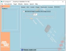
TAB: Advanced
limit internal charger to prioritize other energy sources unchecked

I hope that @sunshine_eggo wants to look at this, when he has the opportunity and time for this.
 
99% sure it's the ESS dynamic cut off settings.

.005C is 4.2A, so if you ever pull less than 4.2A @ 52V, you shutdown - this is about 40%
.25C is 210A, so if you ever pull less than 210A @ 50V, you shutdown.

Why are you using ESS? With ESS installed, there are a bunch of additional configuration changes that need to be made in the Cerbo.

You didn't include your grid setup. Are you backfeeding to grid?

Did you enter custom values in the BMS driver config files?


Just feed data from one BMS and see what happens then, all three batteries will still charge and discharge at the same rates if they are paralleled.

I don't think this will solve the problem, and there is a battery aggregator that's worth pursuing first.
 
99% sure it's the ESS dynamic cut off settings.

.005C is 4.2A, so if you ever pull less than 4.2A @ 52V, you shutdown - this is about 40%
.25C is 210A, so if you ever pull less than 210A @ 50V, you shutdown.

Why are you using ESS? With ESS installed, there are a bunch of additional configuration changes that need to be made in the Cerbo.

You didn't include your grid setup. Are you backfeeding to grid?

Did you enter custom values in the BMS driver config files?


I don't think this will solve the problem, and there is a battery aggregator that's worth pursuing first.
I use ESS to ensure that (when there is enough battery capacity) no energy from the public grid needs to be used.The system is powered by an MPPT 250/70 with 4000wp of solar panels and by means of a Fronius Symo 6.0-3M And a Power One Aurora 4.2 inverter with 4000wp, which will soon be replaced by another Fronius Symo.
In the near future I also want to use Dynamic ESS with dynamic energy contract.With ESS I want to ensure that the batteries can be discharged up to 25% to keep the meter at 0 consumption.The 25% cappaci time that remains is for when the grid fails.

When the batteries are full and the solar panels provide more energy than the appliances in the house need, I feed back into the grid.

The only adjusted value in the config of the BMS is the battery capacity and the charge and discharge power.
InstellingenBMC1 (002).PNG

If I can, I'll adjust the Dynamic Cut Off tomorrow.
For this, the system is likely to go down. And do I have to switch off planned, among other things because of the heat pumps (for heating 3 phase and for tap water 1 phase) they hate an outage in working situation.

Thanks for your help Sunshine! (and Lexio)
 
ESS is complex and flexible, so proper configuration can be very difficult.

I would set the dynamic cut-offs all much closer to 48V, like 48.0, 48.1, 48.2 and 48.3 since you're not actually relying on this for grid interaction or failover.

And yes, most assistants updates force a reboot of the inverters that interrupts power for several seconds.

As far as proper configuration of ESS goes, you're likely more proficient than I am.
 
Last edited:
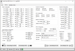
covp 3.60 rel 3.38 if your cell is hitting 3.6 some thing is wrong and your pack needs to be re balanced rel 3.7 3.8 is your cell in rest (warnig to e-mail ?)
cuvp 2.8 rel 3.1 my suggestion you want your inverter to cut the power 48 v rel 3.1 when empty it will bounce back to 3.1 maybe even a little higher so you don't end up in a loop
change pack values accordingly
chgot 35 rel 30 make it not to hot when you charge
chgut 7 rel 8 7 c safer
dsgot 40 rel 35 for the hot summer it is already high

balance starts at 3.45 5mv my values

high protection configuration
what is that ???

else change it at least to 3.65v and 2.6 v
 
Last edited:
yea that ESS is still a complicated story want sell high, but not when it is raining tomorrow.
it is almost a complete new science. :)
 
Hey @DutchCookieMonster I'm not sure on 3phase or ESS setup, but if you have 3 x BMS are you using:

https://github.com/pulquero/BatteryAggregator or similar, to aggregate each BMS/Battery? Allowing the Multi's to charge/discharge with full current for all 3 batteries combined, If not then that might be part of your problem.

Side note:

If you have a shunt too, but want to use the BMS for battery monitoring, you'll need to SSH in and run "dbus-spy" on command to see what bus the shunt is on, the battery aggregator read me is useless, but it works well. When it says to exclude a shunt add "excludedServices": ["com.victronenergy.battery.shunt1"] you need to swap the 'shunt1' part with tty7 or whatever bus dbus-spy showed it on.
 
covp 3.60 rel 3.38 if your cell is hitting 3.6 some thing is wrong and your pack needs to be re balanced rel 3.7 3.8 is your cell in rest (warnig to e-mail ?)
cuvp 2.8 rel 3.1 my suggestion you want your inverter to cut the power 48 v rel 3.1 when empty it will bounce back to 3.1 maybe even a little higher so you don't end up in a loop
change pack values accordingly
chgot 35 rel 30 make it not to hot when you charge
chgut 7 rel 8 7 c safer
dsgot 40 rel 35 for the hot summer it is already high

balance starts at 3.45 5mv my values

high protection configuration
what is that ???

else change it at least to 3.65v and 2.6 v
high protection configuration, is something from Overkill Solar. This is included in the default config file by default. I don't know what it's for exactly.
 
Back
Top