diy solar

diy solar

Bottom and top end testing. "Boing!"

venquessa

New Member
Joined
Apr 8, 2023
Messages
219
Location
UK
With the weather we get here (Northern Ireland) bottom end testing a solar storage system is easy. Today/Tomorrow I should get some top end testing done.

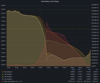
This was my first bottom end test of the 4S 105Ah LFP (Varicore) cells.

It's "as is". Open to interpretation. I'll give mine, but I others with experience will know more than I about how good, bad or terrible it actually is in the grander scheme of things.

boing.png

I just didn't turn the loads off when I would normally do so. I just let it run until the BMS proved it would do as it should.

The highlights in the first half are:
* just how steep that "cliff" becomes below whatever voltage. We knew this.
* the absolutely shocking state of the bottom "balance" or lack of it on these cells.
* The BMS does indeed kill discharge instantly (by the graph resolution/sampling) at 2.599V

The second part is more interesting. Figuring I might as well test the balancer out, I set it to "Always on" with a 5mV tolerance and left it to see what happened. The worst case in my view at the time was a cell would be pushed down to 2.5V and the BMS would shut itself off as well and I'd have to go out and reboot it in the morning.

That test, in my opinion, running the balancer at the bottom end was a complete failure on the BMS's part. It looks like it is "dumb round robin fly capacitor" balancing, going cell1, cell2, cell3, cell4. Unfortunately poor cell 3 never really gets his "fair" share of cell 4s excess and the balancer drives it into a LVC state again. It is at least reassuring a little that it did not simply repeat that mistake over and over.

In fairness, it did get the cells in balance just before dawn. However, I will be returning it's setting to upper top region only.

Unless I have good reason to or it happens by accident, it's probably the last time I produce a graph like this.

We have two days of sun, maybe today I will see what happens to that bottom balance when it reachs the top. I have no high expectations for these cells, but I expect the balancer to get a work out.

Other notes: The MPPT control did go off line given not even a few mA trickle from the BMS. When the BMS recovered at 2.65V the MPPT did power back up again normally. However during that second "BUMP" at 2.6V the MCU on the MPPT ModBus port crashed and did not recover, most likely brown out. Just data loss and monitoring glitch on the MPPT side. No biggy it was still functioning as an MPPT.
 
That is a great post - thanks for sharing.

I have an inductive balancer, and it keeps the cells close as they approach the bottom of their capacity, but if your load exceeds the capability of the balancer nothing is going to stop the cells deviating at the very end.

Looks like your system is working well - I think that graph would be typical of most systems.
 
I did get a top end test. It was worse than expected. Cell 2 and 3 (AGAIN!) shoot off together and HVC'd the BMS, 3 times in a row. Sun went away.

The JK-BMS does not seem capable of hanling large imbalance. It just seems to wander around and certainly not focus on the worst cases. I watched it perfectly balance the middle two cells and leave the two outer ones 100mV out!

I installed the little Heltec flying cap balancer and immediately it went to work on the large imbalance and had it fixed in several hours.

Those little Heltecs have their own issues, if I understand the reviews. So if it is to be used, or if it looks like it might be needed, I will install it with a "smart switch", such that I can engage it only if/when it's needed.

No data though, as I got impatient and installed the other 4 cells, swapped the BMS for it's bigger brother and rather than create new graphs, being lazy, I just repointed the old ones. The data is still there, I just need to duplicate all the graphs again. (That little BMS will return with 6 tiny little cells in the future).

I will just do the topend tests with the 24V pack. Needless to say, as it just got built, the balance is an ongoing operation.
 
Having my system limit charge current as the first cell reaches balancing voltage is one of its most important features, and eliminates top balance issues.

Unfortunately it is more difficult to control loads at the low end of the SOC. At this stage the best i have come up with is to have non-critical loads on a SOC controlled disconnect, so only essential loads are in use below 40%SOC.
 
Having my system limit charge current as the first cell reaches balancing voltage is one of its most important features, and eliminates top balance issues.
Jealous of the "outer loop". I am used to having that in "small battery land". How do you achieve that?

I'm sure there is a way. The question is, given it sounds so simple to do, even in a very high capacity system. Why don't all BMSs doit.

I can do it digitally. However that can never be considered 100% reliable. So the 'dumb' defaults have to conservative and the digital control "weak".
 
Last edited:
Jealous of the "outer loop". I am used to having that in "small battery land". How do you achieve that?

I'm sure there is a way. The question is, given it sounds so simple to do, even in a very high capacity system. Why don't people do it.

I can do it digitally. However that can never be considered 100% reliable. So the 'dumb' defaults have to conservative and the digital control "weak".
Most lithium battery systems have the BMS control the charge current.

A lot of DIY systems are put together with low up front cost in mind, cheaper components don’t always have the best functionality.
 
Jealous of the "outer loop". I am used to having that in "small battery land". How do you achieve that?

I'm sure there is a way. The question is, given it sounds so simple to do, even in a very high capacity system. Why don't all BMSs doit.

I can do it digitally. However that can never be considered 100% reliable. So the 'dumb' defaults have to conservative and the digital control "weak".

@toms might disagree with me, but one can basically get the same effect with a 3.45V absorption voltage. While the initial current is uncontrolled, the lower absorption voltage causes the current to start tapering sooner and over a longer period of time.
 
@toms might disagree with me, but one can basically get the same effect with a 3.45V absorption voltage. While the initial current is uncontrolled, the lower absorption voltage causes the current to start tapering sooner and over a longer period of time.
I agree with you, and a lot of systems are setup that way.

The drawbacks with this are:
- longer charge time (meaning you need more PV for the same charge)
- no ability to limit charge current based on temperature
- no ability to limit charge current at low SOC
- there is still the risk of cell HVD shutting down the system, this increases with cell age. (active balancing mitigates that - but can carry its own risk)

I have setup systems both ways (my current supplementary pack doesn’t control charge, just has a minitactor on the PV input to the MPPT).

Each system needs to be matched to the users specific requirements.
 
one can basically get the same effect with a 3.45V absorption voltage.

Interesting point. I put the second set of cells into service, as they are going in series I am left to balance them initially. My first finger in the air was way out, so I spent the day manually balancing them. The sun helped me until about 2 o'clock when 3 cells went skyward, HVCd, which was expected. Still testing I watched what it did in the "abnormal" situation.

Not exactly good. The HVC voltage overshot to 3.685V several times. Based on the futile repeatitiveness it did this at, I intend to significantly lower my "HVC recovery" voltage. It's set to HVC at 3.65V and recover at 3.60V. I'm going to move that down to 3.5V or maybe even 3.4V "If it HVCs, leave it alone and let the balancer have a good crack at it before firing it up again!"

At the end of the day I still had 3 cells low, 5 normal. 100mV delta. So I put the charger on 28V and watched it, started at 13A but fell to 3Amp after 10 minutes. The high cells went higher but they tapered off around 3.5V and as the balancer slowly corrected it came down towards 3.4 while the low cells rose. This morning it's all within 0-2.5mV. Will see how that pans out when the sun hits the panel.
 
So, I was hoping to have continuity between these tests, continueing with the top end tests.

However, in between times the system has been completely tidied and rewrited and the MultiPlus installed.

In the end I gave up on the sun for top end testing and decided to test out the Multiplus to help with the top balancing.

After some fussing around getting the remote VRM config upload working so I didn't have to go to the garage with a PC to set the charger voltage/current... I configured the charger for Lithium with the default settings. Max charge 12Amps and 28.40V

That worked brilliantly until, as expected a cell took off upwards. A cell over-volt occurred @3.65V. The cell settled and the charge re-enabled and repeated this 3 times before switching into "Float" at 27.6V I think by default.

Now if I was to do this again, I would have just left it there overnight. There was still a chunk of imbalance present at that float voltage. It would "soak out" with the BMS balancer by morning.

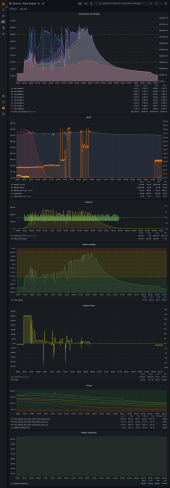
Instead I choose to keep reconfiguring the charger limits to coax it to where the highcells would stablise in the 3.4-3.6 region but not HVC them, giving the BMS plenty of time to fix the imbalance. It took hours and hours and I think I uploaded about 35 different configs, but... I got there. The trick was actually to lower the max charge current to 3 Amps. Let the first HVC happen, but make note of the pack voltage as it passes 3.6V. Set the charge max voltage to that pack voltage and reset. Once I got it stable without HVC at around 28.0V, 2 more cells joined the top cell and the max cell voltage fell to 3.55V, then another 2 joined them. I adjusted the charger up to 28.40V and after a few bumps into the HVC it settled with 1 very slow cell. In the end I gave up switch it off and went to bed.

You can see me using the DC loads to slow the onset of HVC... and failing. Also using a 250W heater on the inverter to bring the cells down and reset the charger input on the BMS. (Janky!) I would not consider this a "normal" top of charge. It's just top balancing the lazy way.
1682343026200.png

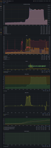
Was it all worth it? Well this is how the full sun did today against the top balance. A nice capture at 28.80V minimal imbalance <10mV and after an asborb for 2 hours it dropped to float at 27.0V undershot a little and recovered nicely in "load following". Success!

1682343285260.png

In the proceeds of doing this with the Multiplus I learnt quite a bit about it's ways. Nice bit of gear. Just need to have a word with it around when it should use the AC input and when it shouldn't, similarly the charger. If I can get it set up right I believe it will provide 2 way redundancy for both DC loads (the battery charger) and AC loads (grid vs. inverted).

Interactive grafana snapshot link:
 
Last edited:
That is kinda the way i go my 4 batteries balanced.
I am using a heltech active balancer with a voltage switch on the on switch.
Once i see 27 volts then it turns on. a 5 amp balancer does 1 amp of balance currant for 100 mv or cell difference.
The first few time it had adjust the max voltage and let it work. I am using home assistant to control max charge currant when the
batteries reach 95% state of charge. At 3.5 volts on any cell to further reduce the max currant.
It working pretty well now. A few days of good sunshine last week and it doing its thing without my help.
I am using solar assistant to get the data to HomeAssistant
 
Nice. HA refuses to pick up the vast majority of my energy counters, so the energy dashboard only shows the grid monitors and plug sockets.

I've went through a few more absorptions with both solar and the Multiplus charger. After the battery had drifted around 50% for a week, going up during the day and down at night, the 10A of the multiplus hit the HVC 3 times in a row before it settled back down. I've lowered it's target charge voltage right back to 28V. The panels do a better job at the top end to 28.80V.

Yesterday I had the spark out. Full day including labour and parts £300. Panel and rails installed on garage roof, AC Island consumer unit installed. AC power supplied to the office where it powers one plug socket with extensions.

I think the cheap cells which claim 105Ah are probably more like 70Ah in practical terms. I'll have to invest more time and probably money getting better ones next time.

However, since about 9am the current flow is "into" the battery, even though I am consuming 170W of AC power, running my office! The 330W panel peaked momentarily at 401W in the brief moment of blue sky. So I'm still "netting" 20-50W on an overcast day while running the 180W of the office, including a 43" 4K HDR1000 monitor, 15W mini PC and a bunch of lights.

Well impressed.
 
HA is great. For me however it's a secondary thing. I don't use it for "automations" as I am a software engineer by trade and it's actually a lot easier just to do the automations in Python directly than faff around with HA's abstractions and other non-sense. I suppose somewhere in between them in Node Red.
 
Back
Top