As noted above…
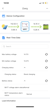
You are having some SERIOUS voltage drop under load between the SCC and the battery. That is is big problem!
Your system will never be right until that is figured out. You can mess with float - boost - bulk, but the voltage drop is the real problem…
How to fix voltage drop…
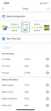
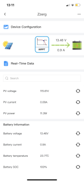
One (or more) of your connections or components between the lugs of the mppt and the battery terminals are causing a voltage drop of 14.14 - 13.35 = .79volts!!! If it was working correctly it should be .1v or less. Your issue only shows up when under load. Your wires on your drawing are plenty big. ( if anything they are bigger than needed - so good job there!)
Two ways to track the issue down… with your DMM(digital multimeter) set on ohms, test each wire and connection on both the positive and negative paths - you are looking for high resistance.
With the DMM set for Dc volts, and the SSC charging at 14 volts, test each connection and find out where the .79v drop is happening. It could be a little here and a little there. It could be a component like the breaker or a crimp on a wire.
One other item… your three panels are in series, anytime one panel has a shadow- all three panels are effected. On RV’s it is usually best to have the panels in parallel if possible. You will need a 3-1 MC4 connector and three MC4 fuses (on for each panel - 15a will be fine). That will help because as long as one panel is in sun - you will get good charging into the battery. Your wire from the panels to the SCC is at least 10awg - correct?
To try to answer your last question o boost voltage- I cannot - that is the programming inside your SCC. I use a Victron mppt SCC - so it has different programming. That’s why earlier I asked what your owners manual says about that setting. It programming logic may be different than what you expect.