diy solar

diy solar

Bridge rectifier as a blocking diode

Ilkkka

New Member
Joined
Oct 27, 2021
Messages
5
Hi everyone, newbie here!

I'm wanting to connect 280W solar panels in parallel and use bridge rectifier diodes instead of common schottky blocking diodes. This is because large enough schottky's are not readily available where I live.

So, do I connect positive and negative leads coming from the panel in to rectifier AC-terminals and then leads going to MPPT-charger in to rectifier DC-terminals?

Or, like it's usually done with schottky's that only the positive lead from the panel is connected. And in this case it would be connected in to rectifiers DC positive terminal and then MPPT-charger lead in to DC negative terminal (leaving AC-terminals "empty", without connection).

Thanks for your help. Sorry my terminology might not be up to standards as I'm still learning the ropes.
 
I'm not getting what you are trying to accomplish, unless you feel the need to drop more voltage, and waste the additional power from the current flowing across that greater drop, times two, if you use a bridge configuration. Where I want diodes (I do, because I have assorted cheap communist Chinese DC-DC converters hooked up here and there, and I'm not confident that current is always flowing the right way), you probably want to find a Schottky, and only on one side, unless you don't need it at all- I have panels in parallel and series (only 6, so far, on a 24V system, perhaps it doesn't apply to what you are doing) with descriptions which said they had diodes internally, so I just hooked the panels up and when I didn't see any trouble, I called it good enough for government work (a standard which I suspect might be rapidly becoming more easily met as I write).
 
Thanks for your replys, guys.

I wanted to avoid a lengthy post and keep my question simple, but here goes; I've got two 280W panels wired in series on the roof of my cabin. They will be covered in snow from approx. December till March.

I recently bought one more 280W panel which is now mounted vertically on the wall and will be snow free. This panel's function is to keep the batteries charged over the winter. I have no access to the cabin in the winter.

My charge controller is 100V/20A so I can't hook all panels up in series which leads to the vertical panel being parallel with the two panels on the roof.

All panels not pointing in the same direction, and two panels on the roof not getting any sun for at least three months, I need blocking diodes.

Bridge rectifiers were readily available so I bought them. I'm not too worried about a small voltage drop either.

Let me know what you think. Cheers!
 
Why steal diodes from a rectifier? On my van, one panel slid under an other when traveling so it needed a blocking diode. Amazon had MC4 fuse holders with a diode inside. $6 or $7 each. Just snaps in place.
 
Like I said in the OP, where I live, all fancy bits and bobs are not that easy to get. And at the moment, I don't have time to wait for stuff to be delivered from abroad.
Actually a local battery shop had diode-mc4-connectors but they were 22 dollars a piece and only 8 amp.
 
I don't have time to wait for stuff to be delivered from abroad.
I hear you. It came from New England, took less than a week. Meanwhile, the panels worked fine without.
I sure miss Badger Electronics and Radio Shack though they were pretty useless their last years.
 
Sorry, I don't mean to spam but I really need some guidance before I leave my cabin.

Seems like the bridge rectifier could be hooked up either way; only positive lead from the panels or both, positive and negative.
But does it make a difference which way I connect things?

Cheers!
 
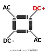
Yes, bridge rectifiers (of sufficent current rating) are fine. A bridge rectifier contains four diodes; you can use two of them inside a single rectifier in your situation.


r.jpg

Take the positive lead from the string from the roof to one of the AC inputs on the bridge rectifier. Take the positive lead from your ground panel to the other AC input on the bridge. The positive output of the rectifier ("DC+" above) goes off to your solar charger's positive input. Leave the negative pin of the bridge rectifier disconnected.

Don't run the negative leads from the panels through any diodes. That introduces extra voltage drop you don't need.
 
Yes, bridge rectifiers (of sufficent current rating) are fine. A bridge rectifier contains four diodes; you can use two of them inside a single rectifier in your situation.


Take the positive lead from the string from the roof to one of the AC inputs on the bridge rectifier. Take the positive lead from your ground panel to the other AC input on the bridge. The positive output of the rectifier ("DC+" above) goes off to your solar charger's positive input. Leave the negative pin of the bridge rectifier disconnected.

Don't run the negative leads from the panels through any diodes. That introduces extra voltage drop you don't need.

Thank you! Didn't even cross my mind running all panels through a single rectifier. (y)
 
Thank you! Didn't even cross my mind running all panels through a single rectifier. (y)
I was looking for that picture (or one like it), but kept getting interrupted by other things at my office. Basically, you connect the positive on the bridge to the positive on the solar controller, and, if you were to use it as a bridge, the bridge negative to the controller negative. The other two (AC input) are the input from the panels, and since it's a bridge, either polarity would work. But if you connect the panel negatives directly to the controller as suggested, instead of through the bridge, (a possibility I didn't think of when I commented earlier), then the problem I had mentioned of adding an extra diode voltage drop (by using a bridge as a bridge) does not occur. In that case the positive from the panel can go to either of the AC inputs, while the negative from the panel remains attached directly to the negative on the solar controller.

One nice thing about using a bridge is that if you burn out a diode, you can reverse the polarity to the input and use the other diode.
 
Bridge rectifiers are very cheap and robust, and the higher current ones that have a metal case can be bolted to the framework to dissipate the heat generated.
As mentioned above by mbshoe, just use three of the connections on the bridge on the positive side.
The three negative wires then just all join together without being connected to the bridge.
 
Back
Top