diy solar

diy solar

Building a truck camper charging system built around Orion Smart

jsackspot

New Member
Joined
Apr 4, 2022
Messages
14
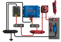
I looked at the Explorist Life's diagram as the penultimate version I'd build out (and be able to move to a van or whatever scenario). That version has a Multiplus, solar arrays, and AC/DC outlets. For now, I'm trying to go lean, so help me validate my meager build:
  • 100Ah Litime (can add parallel power, mid- to near- future), negative wired to:
  • SmartShunt
  • fused MRBF 300A on the battery (so I can scale up)
  • 6AWG wiring to:
  • Orion Tr-Smart 12/12 30, wired to:
  • 60A MEGA fuse to alternator (meaning truck battery)
  • Blue Sea fuse panel for distribution (lighting, fridge, chargers, etc.)
Phase II would be Lynx Distributor, wiring, cutoff switch, MPPT 100/20, connectors for permanent roof and ground solar connections. I know a lot of the components are higher-capacity, but it's the buy-once-cry-once vibe. Phase III would add the Multiplus, AC, etc. I know I'd have to upgrade the wiring, but I'd just rework mounting the components anyway. Mounting on some HDPE temporarily for now, as the camper gets more built out.

Would you add/change/delete anything in my build? Your thoughts appreciated. Thanks!
 
Last edited:
A fuse is to protect the wiring.
The MRBF 300w fuse will not do anything useful for you. The BMS in the battery will only produce ___amps (probably 100a - maybe 150a - see your spec sheet). It has 6ga wire on it. It should be sized for the 6ga wire (my guess is about 80a - but that needs verification). So that fuse needs dropped. When you put in larger wire (and more batteries) then buy the fuse to protect that larger wire.

I added a Victron Smart Battery Protect (BP-65), that goes to the fuse box for all lights, etc. That way if something gets left on and the battery drains it will shut off at ___v (user select- mine is 12.4v) rather than all the way down to bms cutoff.

Good Luck with your project
 
Reusing this throwaway post to put up 0E5B1957-03B5-45EE-9AEC-32FFB865E871.pnga draft of the diagram with actual components, perhaps not exactly the orientation, but roughly. It’s definitely a temporary layout as more components and wiring get upgraded.
 
Last edited:
Are you planning to run an inverter at all? If so I'd recommend getting that into your design from the start so that the cables and fuses are sized correctly.

Source - My truck camper solar build initially did not include an inverter so everything is 6AWG. Now that I have an inverter (Victron 1200 VA 12VDC) that cabling is too small and I need to redo it.
 
I will eventually and did plan on either converting the wiring and remounting all the components anyway, and potentially going 24V.
 
I would figure out the system voltage from the start. You'll save yourself a lot of money and time.

Is this a slide-in truck camper? If so, what amp draw are your jacks? If they're sufficiently high, you may want to stick with a 12 volt system. Otherwise you'll need to include a hefty 24-12 converter to run the jacks.

When designing the system, it's important to leave enough room for wiring. Cables will bend only so much. Welding cable is much easier to work with due to how pliable it is.
 
I’m doing this in phases, so it’s just a rooftop tent and the components (diagram above); they will be temporarily mounted for a season or two for a fridge and lights. Eventually it will be a cab-over type like Super Pacific or others. Once the camper is in place, I will go to the second phase with an MPPT (potentially sooner), some on-the-go panels and fold out panels (and decide to go 24V, wiring, etc.), then eventually end with the Multiplus II, Lynx, Cerbo, shore connections, 300-400Ah, induction(?), probably 3-4 years out.
 
Last edited:

diy solar

diy solar
Back
Top