diy solar

diy solar

Building Battery Box for my 24v, 200ah Lifepo4 Battery Bank

TedH

New Member
Joined
Jun 5, 2020
Messages
186
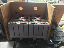
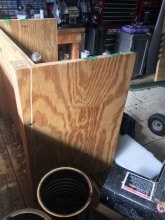
This weekend, I started measuring and drawing up my battery box. The box will be nearly at floor level in my RV but it will rest on a 3/4" sheet of plywood sitting on 4, 1.5" square studs spaced about every 4-5" for support of the roughly 150 lb bank (16, 3.2v, 100ah lifepo4 CALB cells). The 'box' will be mounted to the wall that is shared with my refrigerator and will be screwed into the plywood flooring so it will not move. It will have a 2-piece wooden lid that can double as a shelf (or seat) and will be located within 2 feet of the bus bars that attach to the solar electrical system.

The box will be insulated with spray foam insulation. I will set the batteries inside a heavy 'leaf bag' and blow the insulation in around it. The batteries will rest on a thin layer of padding for minimal vibration absorption. The 2 piece lid will have push-to-release latches so no need to have handles protruding. The height will be about 20" high from floor level (give or take) accounting for 2.75" of base, 10" for battery, space for BMS and some dead space above the batteries and BMS for the heaving wires and necessary mini bus bars to connect the negative leads to/from the two BMS. The batteries will be secured with band clamps around the vertical sides (not on top) so they will all be fastened together not only with the bus bars on top but with good band clamps (3 or 4 around the perimeter of the cells). BMS, SCC and Inverter temperature sensors will be positioned according to manufacturer instructions. There will be padding above the battery bank also inside the two hinged doors.

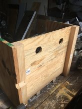
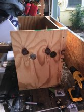
The box will be strong enough to support a large person sitting on (or other heavy object) and will be vented on top and bottom to allow for some air flow. It will be OUT of all weather and since it will be in the house area, should require little to no heat other than the interior heat of the bus. The insulation should help with any spikes in heat from when the bus sits and soaks up the sun's rays. The location is immediately next to the wheelchair lift platform and was occupied by a single 12v SLA battery that was in use for the 12v house systems. So, I am reusing the former SLA battery space for the Lifepo4 batteries. I will be re-wiring the 12v house power source to draw from a fuse panel connected to the 24-to-12v converter that will be powered off of the 24v system.

Footprint is approx. 27-inch L x 14-inch W and 20-inch High.

I am refining the drawings and will post pictures when finished. Two week plan start-to-finish.
 
Last edited:
...The box will be insulated with spray foam insulation....
I just found out Class 1 fire-rated foam is available. Posted about it here and also learned the DOW stuff is available from Lowes/HomeDepot.
 
I use the Great Stuff. According to literature: Is great stuff fire resistant?
FEATURES: FIRE-RATED: GREAT STUFF PRO has been evaluated by ASTM E 814* in wood frame pipe penetrations. Conforms to the ASTM C557-93, D6464, CA25-4, and is UL Class 1 (Flame spread of 15, smoke of 20). Fills, seals and insulates gaps up to three inches.

I filled my window openings with the 2" thick white styrofoam board with Great Stuff around the edges. Worked great.
 
do share your plans... I too am working on a box design. However at the current time, I will have it mounted on the front of my TT. So I'm adding some Pink insulation to the inside of the box for thermal protection. Design is still in the works. Does not seem to be any suitable production boxes, tool boxes, or other storage boxes with the dimensions of my 280ah batteries and 1 or 2" insulation around the outside. I'm thinking custom made at machine shop, but that is $$$$$
 
I looked high and low and came up empty on reasonably priced, ready made boxes that fit the footprint I wanted to put them in. I figured that since I am securing it to the (wall and) floor, I may as well build it to my specs.

Will post the specs soon.
 
Joining the conversation.....my current project is similar and hoping to see all possible ideas :cool:
 
The bms is roughed in. I need to secure it then install the 2nd bms and attach the two packs in parallel.
 

Attachments

  • 34283FC7-8251-4DA9-8294-F19C890262EF.jpeg
    34283FC7-8251-4DA9-8294-F19C890262EF.jpeg
    68.6 KB · Views: 31
  • 04D16B67-C725-413A-95EF-9FEA2C77BCDF.jpeg
    04D16B67-C725-413A-95EF-9FEA2C77BCDF.jpeg
    143.8 KB · Views: 31
  • BF0D16E2-80AF-41A8-8A75-A0E3CBF8C2E5.jpeg
    BF0D16E2-80AF-41A8-8A75-A0E3CBF8C2E5.jpeg
    125.2 KB · Views: 26
  • F033F176-C7BC-438D-9C75-69ADD0ECC3B0.jpeg
    F033F176-C7BC-438D-9C75-69ADD0ECC3B0.jpeg
    125.7 KB · Views: 31
I need to do something like that for my 8S Eve 280 AH batteries. Except since these are aluminum cased prismatic cells I need to provide a mechanical way of preventing the cells from expanding when charging.

I think 3/4" plywood plates should strong enough. Plus add a piece of plexiglass across the top to protect the terminals from being shorted out. I see people using 1/4" aluminum plates and threaded rod which would help a bit with cooling. Plywood would be a heck of a lot cheaper and easier to work with. I could reinforce the plywood with aluminum Unistrut used as stretchers.

 
Sketched up what I am thinking of.
 

Attachments

  • Eve280 Enclosure.pdf
    81.4 KB · Views: 106
yes you can use the Uni strut, we use it at work to make a frame for everything. Its a bit expensive though. Defiantly wont budge, good and strong
 
yes you can use the Uni strut, we use it at work to make a frame for everything. Its a bit expensive though. Defiantly wont budge, good and strong
I can afford a single 10 ft long piece. How does the aluminum unistrut compare for bending strength? Should I stick with steel?
 
This weekend (Thurs-Sun), I completed the installation, connection and initial monitoring of my 24v, 200ah solar power cell. As I may have mentioned, at this time, it is just the LifePO4 battery bank, AIMS Pure Sine Wave 6000watt inverter/charger and shore/gen power. The inverter/charger has automatic transfer switch to run off batteries or shore/gen. It is set to BATTERY priority. When on battery, I am seeing equal power draw from the two, 24v, 200ah packs (8, 3.2v, 100ah CALB cells in each of the two packs that make up my solar power cell). NOTE: I ran #4 cable to/from the power cell. Both positive cables are equal length. Same goes for the two negative cables. This is VERY important to ensure balance across the battery packs and allows multiple, parallel battery packs. I have two parallel 24v, 100ah packs for a 200ah solar power cell.

From my monitoring Sunday and after an overnight with light load:
  1. The mosfets on the two ANT BMSs like to get hot when charging the batteries. I am planning to add a pair of 'computer' cooling fans to blow air thru ports that I will cut in the box immediately behind each BMS. I have the space. For now, I am keeping a box fan blowing air into the power cell to keep the heat down when charging. I am keeping load low when I am not in the bus. Right now, I am seeing 150-200watt per pack (depending on if the mini-split is blowing... the temps are dropping here and I switched it over to heat pump).
  2. Two BMS - I have two ANT BMS. One is the 7s-16s, 320amp and the other is the 8s-20s, 320amp. The 8s-20s will suddenly show alarming low voltage on #5 cell. When I put the FLUKE meter on it, it reads same/close to the others. The #5 low voltage climbs and returns to close to the other cells and then, out of the blue, it drops to under 2v. I suspect the mosfet is bad. However, I do plan to check the connector for loose/faulty connection at battery and on the ribbon connector at BMS. I have a backup (new) 7s-16s that I bought for this possibility and just have to prepare the harness (connectors, shrink tube and labels). I have a 4th 7s-16s BMS coming as I ordered another set of 16 cells (8 to add another 100ah and 8 as spares/option to add a 4th 100ah string).
  3. The inverter/charger - when the BMSs got hot during a charging session and shut down, the inverter didn't switch to shore; it appeared to protect and choose to shut down. I shut off all breakers/load/inverter switch, let it cool and then reset. This was mid-day Sunday. I then positioned the pedestal fan to blow on the solar power cell and observed the cells stayed cooler and the inverter switched from batteries to shore several times. I had the mini-split blowing AC, the fan, light and on-board air compressor for bus leveling running and was drawing 1000watts from each pack steady.
  4. Battery capacity - I am seeing the inverter doing a good job of charging the batteries but I am not seeing it reach the 28.8 LifePO4 capacity/target. It is set to Lifepo4 on the charger selector. I did boost the charger power after the charging session so I am seeing a steady 45amps (90 total) to each battery pack. The cells are rated for .5C so I am pushing about .45C to them. If I do add a 3rd or 4th pack, then the charging will drop to .25C per pack. That may be a concern (time to recharge) once I am powering with solar. For now, it is not an issue but something I will need to consider. I suspect the ANT BMS or the Inverter/Charger are limiting the total charge allowed into the cells. It may be due to my upper charge limit on BMS (keep below 90%). It gets to about 3.4v/cell before switching back to Battery power (the last charging cycle I observed on Sunday).
  5. ANT BMS monitoring - the Bluetooth app ROCKS! There are more parameters than I could imagine. I have tried to set the critical settings to manage DOD, max voltage and min voltage. I need to make note of the different menu's, options and values and gain some understanding. Sadly, the downside of the ANT BMS is lack of documentation. I'm sure you could get a book on all of the settings, conditions and reasoning. I will share what I find; if I find anything on the 'net.
More later today. Here are a couple shots from when I was monitoring the system on Sunday.

NOTE: While monitoring, something started to smell hot. It was the trouble light against the plywood. I moved it. Otherwise, nothing getting so hot that damage is a risk. I am performing checks with my FLUKE meter on all cables. Glad I used the #2 on the inverter. It pulls/pushes some serious amps.
 

Attachments

  • IMG_1798.jpg
    IMG_1798.jpg
    140.5 KB · Views: 62
  • IMG_1799.jpg
    IMG_1799.jpg
    80 KB · Views: 62
Last edited:
There is spray on wood/lumber fireproofing that might be useful for the plywood in/around the battery box. Stuff like the link below. There's probably smaller containers available. MIght be worth considering for this as another layer of defense?


This is the power cell as it was roughed in on Saturday. I have since routed some of the loosely hanging wires and plan to protect with wire looms.
 

Attachments

  • IMG_1795.jpg
    IMG_1795.jpg
    104.7 KB · Views: 77
I did see on a youtube vid, where someone used spray in form as a space absorber around his cells. then laid a plastic bag over the top, sprayed another layer over the top to provide a molded cover for them. pretty cool idea, making it form fit.
 
24v 200ah. I planned to double to 400ah but just overcharged two of the 16 new cells so looks like I will just increase to 300ah with a few spares.
 
Back
Top