


Steve_S
Offgrid Cabineer, N.E. Ontario, Canada
I've read through this thread quickly. I run Hybrid LFP & Big Lead (Rolls Surerete deep cycle) and t works with quirks. I HAD considered used EV packs but the chemistries are too far out of range from life with FLA and after a few months of research went LFP because it is very close to FLA profiles.
Even with LFP & FLA, there are compromises but they can be worked around. I must say, that even so they are close, you have to be careful and watchful because the Low Volt disconnection for FLA versus LFP and of course you should never take FLA below 50% DOD.
For a Twist that no-one mentions. When you have Big LFP cells and multiple packs within an LFP Bank they will level up between themselves (if properly configured). Having a Big FLA bank sitting on side, can actually act as a buffer and provide added voltage which levels up the rest. BUT THE CATCH, You need to be able to either manually or automatically disconnect the FLA bank from the LFP bank when the FLA reaches LVD point or other situations requiring disconnection. There s tech out there than can do this ad even be programmed... it's NOT cheap ! Myself, because I am in attendance all the time, I use a BlueSea 9001e as shown below, NOTE they also have models with AFD (Alternator Field Disconnect) for anyone charging via alternator. BTW: A Side effect benefit if you have LFP cells that wander (most do have divergence) the FLA steadies that somewhat by having that constant current from them and if there is a balancer doing its job (not a passive balancer). I can say, it's nice to look at multiple LFP packs of differing capacities and see all the cells in all packs with 10-12mv difference.
 www.bluesea.com
Even with LFP & FLA, there are compromises but they can be worked around. I must say, that even so they are close, you have to be careful and watchful because the Low Volt disconnection for FLA versus LFP and of course you should never take FLA below 50% DOD.
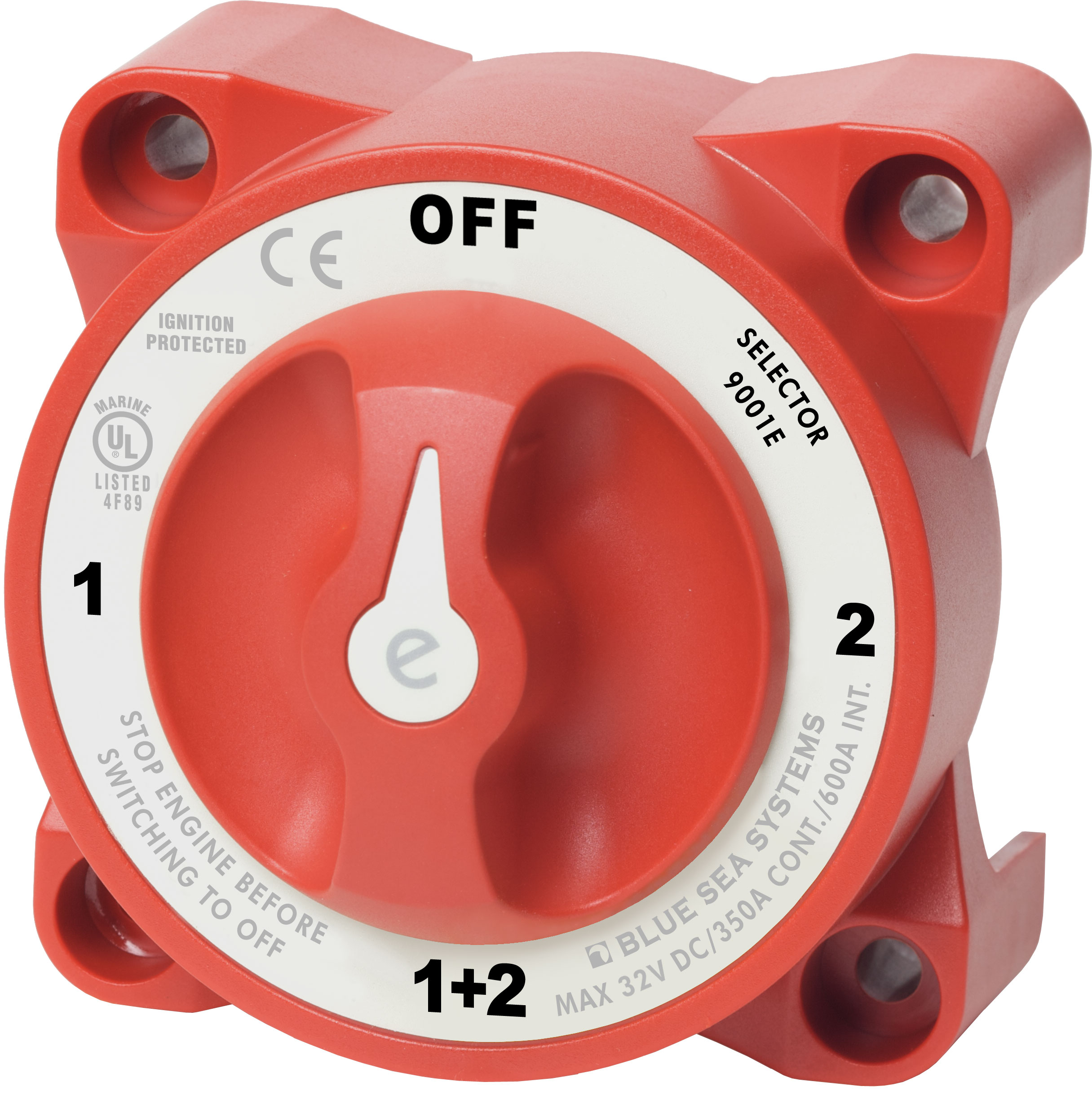
For a Twist that no-one mentions. When you have Big LFP cells and multiple packs within an LFP Bank they will level up between themselves (if properly configured). Having a Big FLA bank sitting on side, can actually act as a buffer and provide added voltage which levels up the rest. BUT THE CATCH, You need to be able to either manually or automatically disconnect the FLA bank from the LFP bank when the FLA reaches LVD point or other situations requiring disconnection. There s tech out there than can do this ad even be programmed... it's NOT cheap ! Myself, because I am in attendance all the time, I use a BlueSea 9001e as shown below, NOTE they also have models with AFD (Alternator Field Disconnect) for anyone charging via alternator. BTW: A Side effect benefit if you have LFP cells that wander (most do have divergence) the FLA steadies that somewhat by having that constant current from them and if there is a balancer doing its job (not a passive balancer). I can say, it's nice to look at multiple LFP packs of differing capacities and see all the cells in all packs with 10-12mv difference.
e-Series Selector Battery Switch - Blue Sea Systems
350 Amps continuous rating for inboard gasoline or diesel engines.
www.bluesea.com