OhmManiPadmeHum
New Member
Hello,
I'm a beginner working out the details of a 24V system for a bus I'm converting to an RV. At this point, I think I've got things figured out for the most part. I really want to ensure my wiring schematic looks good and takes everything into account, most especially safety. Here's the list of primary components I have to work with:
24V System
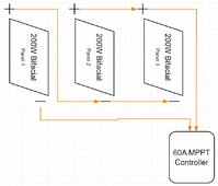
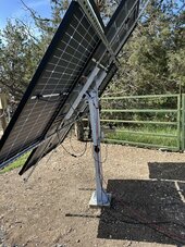
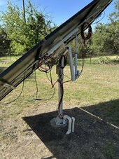
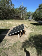
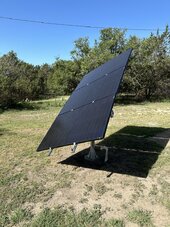
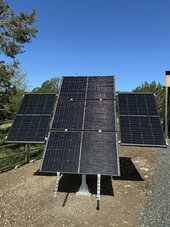
-(3) BougeRV 200W 16BB 24V Panels - https://a.co/d/0igli4zc
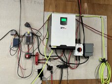
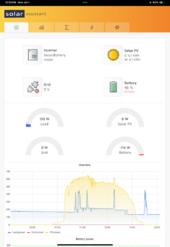
-(1) PowMr 60A MPPT PRO Controller(Max PV in.105V@24V) - https://a.co/d/0gTZYH3B
-(1) SunHooPower 24V 185Ah LiFePO4 Battery - https://a.co/d/05pye5fo (planning on buying another one of these next year)
-(1) 3000W 24V Inverter - https://a.co/d/0e1xFkJQ
I've been doing quite a bit of digging for good information. I have a pretty good idea what sizes I need to connect each component, until I get to the battery->alternator connection. I'm trying my best to follow NEC Codes and Regulations, but I don't have a thorough enough understanding of the difference between 12v and 24v systems, other than 24v is generally safer to run due to lower current and heat
My expected continuous usage is looking to be between 1200w-1800w. I have power tools I'd like to use, so that value could possibly get closer to 3000W.
Refrigerator - ~400W
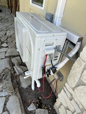
A/C Unit - ~800W
Computer - ~180-220W
TV - ~60W
Charging devices - ~20-50W
With these, it looks like I'll sit around the halfway mark of that 3000W, approx. 1460-1530. This leaves me a good 1500W of room to work with for battery chargers for tools and other tools that utilize AC power. Worst case scenario, I can cut off the A/C while I work with tools, offering a window of about 2300W to work with. I plan on adding some devices a little later on, like an RO system and water pumps(may go with independent solar pumps).
Here's the spec sheet for the BougeRv 200W 16BB N-Type TOPCon
Specs for PowMr 60A MPPT PRO Controller
Rated Battery Current - 60A
System Voltage - 12/24/36/48V Auto
Max. Input Power for 24V - 1440W 37V-105V
Max PV Open Circuit Voltage- 160Vdc
Max. Capacitive load capacity-10000uF
Self Consumption - 0.7-1.2W
Conversion Efficiency - </= 98%
MPPT tracking efficiency - >99%
Temp Compensation - -3mV/degrees C/2V(default)
Specs for SunHooPower 24V 185Ah LiFePO4 Battery
Capacity - 4736Wh
Nom. Voltage - 25.6V
Current Capacity - 185 Ah
BMS - 200A
Max Load - 5120W
Rec. Current Charge- 37A (0.2C)
Terminals - M8 - 9/16"
(according to support")
Max. Voltage Drop - 4.5V
22V after voltage drop
Specs for 3000W 24V Inverter
Rated Input Voltage - DC24V
Nominal Input Voltage - DC 19.5-31.6V
Nominal Output Voltage- AC 115+/-10% V
Rated resistive load - </= 3000W
Peak Power - 6000W
Rated Inductive load- </= 1500W
4xAC provide maximum 800W power output
1000W-3000W, the high-power output terminal must be used as the output link(will probably hook the AC Unit to this)
Wire Sizing:
PV -> PV - 18AWG
PV -> Controller - 10AWG(30') (The bus will be in the shade, with the panels out in the sun)
Controller -> Battery- 4AWG(2')
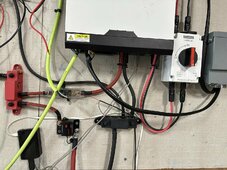
Battery -> Inverter - I decided on 2AWG. I'll have two sections of 5.9" cables for the positive with a 175A breaker. At 1', the voltage drop is approx. 1.43%. 1AWG wire is almost impossible to find on Amazon and 1/0 was getting expensive very fast.
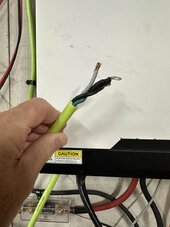
I'm currently trying to sort out how to string together any connections that might help with safety or increase efficiency. I want to be absolutely sure I'm hooking the battery up to the inverter correctly. I've seen examples where there are two cables hooked up to each terminal of the inverter, but where the other end of those cables connected to, I'm lost(this was proposed as the 'correct' way to hook up the inverter, so I'm a little lost there.). I also want to ensure that I have everything grounded properly and may double down on lightning protection.
As far as the components of the system go, I'm worried about using the PowMr Controller and that specific inverter, as they have a handful of one-off reviews labeling them as garbage products. I'm not sure how much of this has to do with a lack of experience hooking them up or if they're actually defective. I could see where things could go sideways if any part of the system thinks it's running 12v, as opposed to 24v, or connecting components in the wrong order(which I've seen in a lot of videos on Youtube.) I still have some time to return those components in the case that any of you might have had bad experiences with them and can confirm what the lower rated reviews are saying on Amazon.
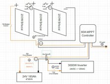
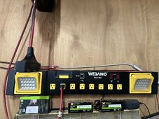
Here's my choppy, basic blueprint for things so far. Some obvious points are, I'm trying to figure out the best solution for handling the negatives, hence the complete lack of grounding. The wiring is very basic at the moment until I can sort out the finer points of the various connections. Any and all insight here will be greatly appreciated.
Thanks in advance for taking the time to read through all this and any help provided. Looking forward to getting everything sorted out!
I'm a beginner working out the details of a 24V system for a bus I'm converting to an RV. At this point, I think I've got things figured out for the most part. I really want to ensure my wiring schematic looks good and takes everything into account, most especially safety. Here's the list of primary components I have to work with:
24V System
-(3) BougeRV 200W 16BB 24V Panels - https://a.co/d/0igli4zc
-(1) PowMr 60A MPPT PRO Controller(Max PV in.105V@24V) - https://a.co/d/0gTZYH3B
-(1) SunHooPower 24V 185Ah LiFePO4 Battery - https://a.co/d/05pye5fo (planning on buying another one of these next year)
-(1) 3000W 24V Inverter - https://a.co/d/0e1xFkJQ
I've been doing quite a bit of digging for good information. I have a pretty good idea what sizes I need to connect each component, until I get to the battery->alternator connection. I'm trying my best to follow NEC Codes and Regulations, but I don't have a thorough enough understanding of the difference between 12v and 24v systems, other than 24v is generally safer to run due to lower current and heat
My expected continuous usage is looking to be between 1200w-1800w. I have power tools I'd like to use, so that value could possibly get closer to 3000W.
Refrigerator - ~400W
A/C Unit - ~800W
Computer - ~180-220W
TV - ~60W
Charging devices - ~20-50W
With these, it looks like I'll sit around the halfway mark of that 3000W, approx. 1460-1530. This leaves me a good 1500W of room to work with for battery chargers for tools and other tools that utilize AC power. Worst case scenario, I can cut off the A/C while I work with tools, offering a window of about 2300W to work with. I plan on adding some devices a little later on, like an RO system and water pumps(may go with independent solar pumps).
Here's the spec sheet for the BougeRv 200W 16BB N-Type TOPCon
| Maximum Power (W) | 200±3% W |
| Open Circuit Voltage Voc (V) | 36.4V±5% |
| Max Power Voltage Vmp (V) | 31.7V±5% |
| Max Power Current Imp (A) | 6.3A±5% |
| Short Circuit Current Isc (A) | 6.6A±5% |
| Solar Cells Efficiency | 25% |
| Power Life | 30 Years |
Specs for PowMr 60A MPPT PRO Controller
Rated Battery Current - 60A
System Voltage - 12/24/36/48V Auto
Max. Input Power for 24V - 1440W 37V-105V
Max PV Open Circuit Voltage- 160Vdc
Max. Capacitive load capacity-10000uF
Self Consumption - 0.7-1.2W
Conversion Efficiency - </= 98%
MPPT tracking efficiency - >99%
Temp Compensation - -3mV/degrees C/2V(default)
Specs for SunHooPower 24V 185Ah LiFePO4 Battery
Capacity - 4736Wh
Nom. Voltage - 25.6V
Current Capacity - 185 Ah
BMS - 200A
Max Load - 5120W
Rec. Current Charge- 37A (0.2C)
Terminals - M8 - 9/16"
(according to support
Max. Voltage Drop - 4.5V
22V after voltage drop
Specs for 3000W 24V Inverter
Rated Input Voltage - DC24V
Nominal Input Voltage - DC 19.5-31.6V
Nominal Output Voltage- AC 115+/-10% V
Rated resistive load - </= 3000W
Peak Power - 6000W
Rated Inductive load- </= 1500W
4xAC provide maximum 800W power output
1000W-3000W, the high-power output terminal must be used as the output link(will probably hook the AC Unit to this)
Wire Sizing:
PV -> PV - 18AWG
PV -> Controller - 10AWG(30') (The bus will be in the shade, with the panels out in the sun)
Controller -> Battery- 4AWG(2')
Battery -> Inverter - I decided on 2AWG. I'll have two sections of 5.9" cables for the positive with a 175A breaker. At 1', the voltage drop is approx. 1.43%. 1AWG wire is almost impossible to find on Amazon and 1/0 was getting expensive very fast.
I'm currently trying to sort out how to string together any connections that might help with safety or increase efficiency. I want to be absolutely sure I'm hooking the battery up to the inverter correctly. I've seen examples where there are two cables hooked up to each terminal of the inverter, but where the other end of those cables connected to, I'm lost(this was proposed as the 'correct' way to hook up the inverter, so I'm a little lost there.). I also want to ensure that I have everything grounded properly and may double down on lightning protection.
As far as the components of the system go, I'm worried about using the PowMr Controller and that specific inverter, as they have a handful of one-off reviews labeling them as garbage products. I'm not sure how much of this has to do with a lack of experience hooking them up or if they're actually defective. I could see where things could go sideways if any part of the system thinks it's running 12v, as opposed to 24v, or connecting components in the wrong order(which I've seen in a lot of videos on Youtube.) I still have some time to return those components in the case that any of you might have had bad experiences with them and can confirm what the lower rated reviews are saying on Amazon.
Here's my choppy, basic blueprint for things so far. Some obvious points are, I'm trying to figure out the best solution for handling the negatives, hence the complete lack of grounding. The wiring is very basic at the moment until I can sort out the finer points of the various connections. Any and all insight here will be greatly appreciated.
Thanks in advance for taking the time to read through all this and any help provided. Looking forward to getting everything sorted out!