Sorry this turned out to be so long.
There are two things that happen at high state of charge that are detrimental to LFP longevity.
First is negative side graphite anode swells about 11% due to all the lithium ions packed in between the graphite lattice when fully charged. It is called intercalation. This puts stress pressure on the protective SEI layer between graphite anode and electrolyte. SEI (Solid Electrolyte Interface) is a very thin grown protective layer to repell electrons from entering electrolyte which will degrade electrolyte. For normal cell operation, only lithium ions should flow in electrolyte. Lithum ions create electrons transfer in the positive (LiFePO4) and negative (Graphite) electrodes which are then passed to the battery terminals. I will come back to this so remember cell current output demand requires lithium ion flow within cell. The more current demanded, the greater the internal ion flow must be.
SEI normally gets some small cracks everytime a cell is charged. It is regrown on subsequent charging but this regrowth consumes a little bit of available lithium which reduces cell capacity a little bit for every full recharge. The SEI regrowth repair process also thickens up the SEI layer which increases cell impedance to flow of lithium ions. Over time, SEI continued growth from recharge cycles is the primary aging process in all lithium ion cells. It locks up lithum, reducing cell capacity, and increases cell impedance over time.
Second is the higher cell voltage. The greater the cell voltage, the more the barrier is reduced for electrons to jump the repulsive barrier at the graphite-electrolyte interface and enter the electrolyte. This causes decomposition of electrolyte which is the second most significant aging process for all lithium ion cells. Higher temp also accelerates this so maintaining high state of charge in a warm environment results in faster aging.
When you overcharge a cell with higher then 3.65v you encourage electrons to enter electrolyte. Above about 4.3v the rate of electron entering electrolyte really increases. When electrolyte decomposes it outgasses (mostly carbon dioxide) which causes cell to bloat. Second more damaging is other electrolyte decomposition compounds gum up electrode to electrolyte interfaces reducing lithium ion migration paths through the cell increasing cell impedance.
----extra info ----
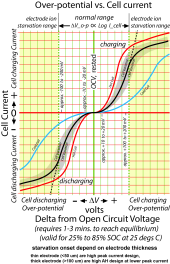
Charging is not just about cell terminal voltage. It also depends on what the bulk charge current is. Back to ion flow. Whether it is charging or discharging, some overpotential (terminal voltage drop for discharge and terminal voltage rise for charging) is required to create a lithium Ion from a lithium atom and move it along through the electrode material, across the electrolyte, and into other electrode. Some of this overpotential is used to break loose the electron to create the ion and some is used to push the ion along.
There is also some pure cell metal conductor IR loss, which is mostly what you are measuring when doing a 1 KHz AC cell impedance measurement with a YR1035 battery impedance meter. This measurement also has some contribution for ion migration movement. It only contributes 5%-50% of actual terminal voltage discharge drop or charging rise depending on amount of cell current demanded.
This overpotential drives the creation and movement of lithium ions. The movement of lithium ions is proportional to demanded cell current. The more the demanded cell current the more overpotential required to create and move the ions.
The relation between cell current and overpotential voltage is proportional to the log of the demanded current. This holds up to the point where the electrodes (anode and cathode material) start to become starved for ions to move due to thickness of electrode material. The onset of ion starvation is dependent on electrode thickness for a given cell design. 'Blue' cells are designed with thick electrodes to give good AH capacity. Their downside is peak current capability which starts to enter electrode starvation at about 0.5 CA of demanded current. Current demand must be met so overpotential must get greater to drive the restricted electrode starved ion movement.
When you charge at higher currents there is more overpotential terminal voltage rise to move greater volume of ions so the 'internal' cell is effectively seeing a lower voltage. This is why terminal voltage is not the complete story of determining when a cell is fully charged. This higher overpotential at higher current also means more internal cell losses and more internal heating.
This is same process for discharging.
3.43v is the magic 'neutral' full charge voltage for a LFP cell. Any voltage above 3.45v with near zero charge current flow is a fully charged cell. The overpotential requires a minium of 10-20 mV above (charging) or below (discharging) the rested cell voltage to create any small cell current. This is why just passively paralleling cells will not fully balance them. The higher SOC cell will end up being about 10 mV higher while the lower SOC cell will end up being about 10 mV lower once they are separated and reach their equilibrium rested open circuit voltage. This net 20 mV rested OCV difference can still have a 30-40% difference in SOC between cells.
Other important item is overpotential shift has a time delay after a demand current is changed. It typically takes 1-3 minutes to equilized but this time increases below 20% state of charge. It also has variance in time above 90% state of charge but there is another factor in that region explained in next paragraph.. Overpotential versus current demand is dependent on temperature. Overpotential versus demanded current starts to really get worse below about 10 degs C. At -20 degs C it is terribly high resulting in a very restricted maximum current capability from cell and terminal voltage collapse effecting ability to pull out AH's of cell capacity.
So why does a cell taken off a full saturated charge at 3.65v not drop to 3.45v. This is caused by a surface charge build up mostly in graphite anode. As cell approaches full charge and charging current drops off, the required overpotential drops. At a constant 3.65v, overpotential is traded for surface capacitance charging. For LFP, this surface charge energy is only about 0.01% of cell's rated AH capacity (28 mA/H for 280AH cell) but can take several days to bleed itself off without any external help. A 1-3 ohm power resistor can bleed off the surface charge in a minute or two. Like discharging an electrolytic capacitor it takes a little time for electrons to diffuse out of the effective dielectric. You should have close to 3.45v once surface charge is bled off.
Now for the uncomfortable revelation, matching AH's and cell impedance does not totally ensure matched cells. Overvoltage at a given current (and temp) must also be matched. It becomes more important if you subject cells to high discharge or charge currents. Packed together prismatic cells at high discharge current results in center core cells having less ability to dissipate heat. Since overpotential is temperature dependent, there will be overpotential mismatch on the bundled prismatic cells. There is a reason Tesla and Battleborn use cylindrical spaced cells.


