ElectricIslander
Solar Enthusiast
We have two strings of nine panels coming to make a total of 18 420WAA Pure R REC panels for a rooftop array that will be connected to a 100A 600V Schneider Charge controller. Each string operates at NOTC at almost 500 V and around 7 amps, so combined would make 14 amps.
There will be four 10AWG wires coming down of the roof in 1" EMT (two +ives and two -ives) and the idea is to have a PV disconnect switch on the back wall of the cabin. The PV wire continues in conduit off to a fire resistant powerhouse with batteries and inverter and generators in separate rooms about 100 feet away from the cabin. As we are in a rural area, installation will be uninspected, but generally up to code.
Although the controller is single channel and has terminals on it's inputs to allow combining strings at the inputs, I wanted to not combine the two strings on the roof but instead combine them in the PV disconnect box so that I can conveniently put a DC clamp meter on each string to see how the two are performing relative to each other.
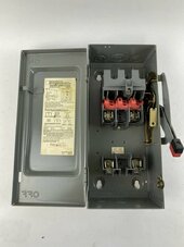
An external PV disconnect is required since the Schneider Mini-PDD we are using isn't rated for 600V. My installer has one of the Schneider Square D H261 Safety Switches seen in the photo, which is a three pole fused disconnect switch rated for 600VDC and 30 Amps. The initial suggestion was to use two of it's poles as the PV disconnects for each positive side and just pass the negative sides through the box.
On reflection though, it seems for safety I might need two PV disconnect switches so I could disconnect both the +ive and -ive on both strings? So we would have a disconnect switch for each string. Anybody know if I need to switch both +ive and -ive or could get by with just one switch on only the positive wires of the two strings?
Or I could combine in the switch box with enough of a loop to access the cables for both strings before the switch and use the two poles for +ive and -ive after they combine.
The rational is that with 600VDC an arc could start to ground from either +ive or -ive (I don't know if the Schneider floats the PV input or references -ive to something near ground potential??). The CC manual just says that a disconnect is required, doesn't say if both positive and negative need to be switched.
Just wanting to be super safe given almost 600VDC in a seaside location. Using fully tinned PV wire and all Stäubli connectors with proper MC4 crimpers.
There will be four 10AWG wires coming down of the roof in 1" EMT (two +ives and two -ives) and the idea is to have a PV disconnect switch on the back wall of the cabin. The PV wire continues in conduit off to a fire resistant powerhouse with batteries and inverter and generators in separate rooms about 100 feet away from the cabin. As we are in a rural area, installation will be uninspected, but generally up to code.
Although the controller is single channel and has terminals on it's inputs to allow combining strings at the inputs, I wanted to not combine the two strings on the roof but instead combine them in the PV disconnect box so that I can conveniently put a DC clamp meter on each string to see how the two are performing relative to each other.
An external PV disconnect is required since the Schneider Mini-PDD we are using isn't rated for 600V. My installer has one of the Schneider Square D H261 Safety Switches seen in the photo, which is a three pole fused disconnect switch rated for 600VDC and 30 Amps. The initial suggestion was to use two of it's poles as the PV disconnects for each positive side and just pass the negative sides through the box.
On reflection though, it seems for safety I might need two PV disconnect switches so I could disconnect both the +ive and -ive on both strings? So we would have a disconnect switch for each string. Anybody know if I need to switch both +ive and -ive or could get by with just one switch on only the positive wires of the two strings?
Or I could combine in the switch box with enough of a loop to access the cables for both strings before the switch and use the two poles for +ive and -ive after they combine.
The rational is that with 600VDC an arc could start to ground from either +ive or -ive (I don't know if the Schneider floats the PV input or references -ive to something near ground potential??). The CC manual just says that a disconnect is required, doesn't say if both positive and negative need to be switched.
Just wanting to be super safe given almost 600VDC in a seaside location. Using fully tinned PV wire and all Stäubli connectors with proper MC4 crimpers.