diy solar

diy solar

Charging method lifepo4 280AH EVE (float or not.)

So even with an low voltage its able to charge to 100% SOC

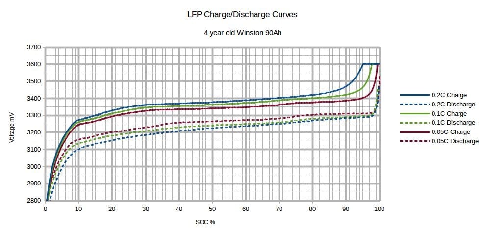
Depending on what rate you charge with, you'll get at the same state of charge at lower voltage.

qidwvcdb3z4i.jpg
 
I agree with all that you said.

But even with your 90-95% range going to 3.5v, it seems at odds with
3.31v up to 3.91v all being labeled as Soc 98%.

I was not trying to make a point, i was just curious what method of calculating/counting was behind the SoC. Its clearly one of the more sophisticated systems around.
This is what it looks like as a whole, the EMS is to the left and has a cover for the enclosure.
20180426_114051.jpg
From the system manual...
The EMS system has everything needed to display the condition and maintain the health of lithium ion batteries and is specifically designed to work with GBS Lithium Ion batteries. The system consists of two major components, the computer (CPU) and the cell sense boards. The CPU shows details about the condition of the battery pack, such as current, voltage, state of charge and individual
cell details, via its video output display. The sense boards form a simple daisy chain by
mounting on each cell to read voltage and temperature; they also perform battery balancing during recharging to equalize the charge within the battery pack. Two alarm
outputs, one for over voltage and one for under voltage, provide automatic shut off
signals to prevent overcharging or over discharging of the battery pack.
A unique feature of the EMS system is ground fault detection. High voltage systems
should be floating relative to the chassis for safety. If an inadvertent path to the chassis
ground is made the system will detect it and display a warning for this unsafe condition.
The EMS outputs composite video to display battery pack information. A CAN (controller area network) interface option is available to output the information from the EMS to other systems.

The system sits at 99% most of the time, it might hit 100% for a brief period but usually sits at 99%.
The EMS up close.
20180426_113026.jpg
 
Boot elec systeem V2.0 Reduced+timer_schema.png
alright this would be the updated version then. a bit simpler than the old one.
ill be using 2 countdown timers which can be set from 0-300H so ill just look at the coulumb meter to determine how long it should charge. and if the coulumb meter is wrong it would just float the system a bit and thats all. so it shouldnt harm it too much. and i want it at 70% so i have 100Ah play room so time wise it isnt that much of an problem to have it charge a few hours longer so yeah this would be an fully manual charger.
cost. 80$
 
The problem with manual charging and no safe guards it only takes one time to get side tracked with something else and you have yourself some door stops or did I miss some level of protection?
 
The problem with manual charging and no safe guards it only takes one time to get side tracked with something else and you have yourself some door stops or did I miss some level of protection?

2x temperature cutoff
2x timers so if one fails to shut of the 2nd will do it.
boost converters are set at an decently low level so even if it charges 24/7 it still wouldnt cause it to go into overcharge it will reduce cyclic life
and it isnt on drawing but i use an 100A DALY bms for each pack. so i guess it should be pretty safe.

Or is there some sort of protection that i am missing?
 
Last edited:
2x temperature cutoff
2x timers so if one fails to shut of the 2nd will do it.
boost converters are set at an decently low level so even if it charges 24/7 it still wouldnt cause it to go into overcharge it will reduce cyclic life
and it isnt on drawing but i use an 100A DALY bms for each pack. so i guess it should be pretty safe.

Or is there some sort of protection that i am missing?
I just got my 2 boost converters. And the plan with the cells is to sandwich them together with soms studbolts. And an steel/aluminium/stainless enclosure. Or just wood. Altho i dont prefer that next to dangerous connections and due to bad thermal conductivity
 
This is what it looks like as a whole, the EMS is to the left and has a cover for the enclosure.
View attachment 14264
From the system manual...
The EMS system has everything needed to display the condition and maintain the health of lithium ion batteries and is specifically designed to work with GBS Lithium Ion batteries. The system consists of two major components, the computer (CPU) and the cell sense boards. The CPU shows details about the condition of the battery pack, such as current, voltage, state of charge and individual
cell details, via its video output display. The sense boards form a simple daisy chain by
mounting on each cell to read voltage and temperature; they also perform battery balancing during recharging to equalize the charge within the battery pack. Two alarm
outputs, one for over voltage and one for under voltage, provide automatic shut off
signals to prevent overcharging or over discharging of the battery pack.
A unique feature of the EMS system is ground fault detection. High voltage systems
should be floating relative to the chassis for safety. If an inadvertent path to the chassis
ground is made the system will detect it and display a warning for this unsafe condition.
The EMS outputs composite video to display battery pack information. A CAN (controller area network) interface option is available to output the information from the EMS to other systems.

The system sits at 99% most of the time, it might hit 100% for a brief period but usually sits at 99%.
The EMS up close.
View attachment 14265
Quite an impressive set up. We have the 400 ah version and I am currently rewiring for better maintainability. I decided to add a few safety items, such as a separate switch for the inverter, and placed the 400a class t fuse as close to the battery + as possible. I did not see a fuse or breaker in your set up. What are your thoughts about this?
 
If LFP batteries are use for a UPS setup where batteries are float charged all the time the charge float voltage should be set to 3.35v per cell.

This will still yield greater then 85% charge capacity from batteries. It is better if you also have a continuously active balancer since a >3.4v triggered resistor dump balancer may not activate.

Dominate issue with continuous charging is continuous growth of SEI (solid electrolyte interface) layer on negative side anode graphite-electrolyte interface. It consumes avalable lithium reducing cell capacity and increases cell impedance.

Assuming a LFP is not 'murdered' due to other misuseage, SEI growth is a dominate reason for cell aging degradation. When fully charged a LFP graphite anode layer will physically increase in volume by about 13%. This puts some mechanical stress on SEI layer causing small fractures. Fractures will be healed on successive recharging but consumes some of available lithium reducing cell capacity and thickening SEI layer increasing cell impedance. Physical stress due to the graphite layer bloating can also cause delamination of the graphite to copper foil negative terminal collector interface increasing cell impedance.
 
Does this mitigate the SEI issue?
Not entirely, only reduce the rate of growth. SEI growth is genetic to all present lithium based batteries. Nothing lasts forever.

SEI layer protects electrolyte from chemical decomposition.

 
Last edited:
With
Quite an impressive set up. We have the 400 ah version and I am currently rewiring for better maintainability. I decided to add a few safety items, such as a separate switch for the inverter, and placed the 400a class t fuse as close to the battery + as possible. I did not see a fuse or breaker in your set up. What are your thoughts about this?
Inside the 5th wheel I can turn on/ off the GBS batteries .

The Magnum remote (Me-Arc50) gives me the ability to turn on/ off the charger or inverter (putting them in standby mode).

For instance when I am hooked up to a 120v power source with the hybrid unit I can set the incoming load share from 0-50a. If it's a 15a source the batteries will pick up the excess power needs if needed. Right now I'm traveling and there was no boondocking spot, pedestal power has 50a service, I set the incoming load to 50a which passes the 120v AC to the 5th wheel (this puts the inverter in standby mode), I'll turn the charger to standby mode so my batteries are carrying misc 12v DC loads and let solar do all the charging or carrying the loads. If 120v power is lose the inverter steps in.
Here you can see the 12v 400a selenoids for over/ under protection. 400a T fuse inline to the inverter. Upper right area is the solar in/ out breakers 48vdc.

20200318_080203.jpg
20171019_143946.jpg
 
Thanks for the details. That’s a great system!
What size copper did you use for the bus bars?
 
I appreciate you sharing these details!
I saw that you use a spreadsheet with data from your system. How do you get this info?
 
Here are the 2 displays.
Right one is for the GBS system which the screen can be switched to all individual cell readings.

Left display is the Magnum system which can be toggled through a lot of screens to see specitic readings from the inverter/ charger or the solar charge controller besides making adjustments if needed.

20201101_071509.jpg
 
Correction for the copper bar connecting the batteries, I measured it this morning.
1/4" thick x 3/4" wide
 
If LFP batteries are use for a UPS setup where batteries are float charged all the time the charge float voltage should be set to 3.35v per cell.

This will still yield greater then 85% charge capacity from batteries. It is better if you also have a continuously active balancer since a >3.4v triggered resistor dump balancer may not activate.

Dominate issue with continuous charging is continuous growth of SEI (solid electrolyte interface) layer on negative side anode graphite-electrolyte interface. It consumes avalable lithium reducing cell capacity and increases cell impedance.

Assuming a LFP is not 'murdered' due to other misuseage, SEI growth is a dominate reason for cell aging degradation. When fully charged a LFP graphite anode layer will physically increase in volume by about 13%. This puts some mechanical stress on SEI layer causing small fractures. Fractures will be healed on successive recharging but consumes some of available lithium reducing cell capacity and thickening SEI layer increasing cell impedance. Physical stress due to the graphite layer bloating can also cause delamination of the graphite to copper foil negative terminal collector interface increasing cell impedance.
I'm thinking about doing this but I don't have any conception of how much it will impact the life span of the battery.
Can you help me to understand the impact?
 
I have 32 cells of 3.2v LF280ah Eve batteries and just about to install them and would like to know charging parameters for Bulk, Absorption, and Float. According to paperwork i see bulk should be 14.6v (3.65v x 4) running a 12v setup. Any help would be appreciated.

Michael
 
If you are running those 32 cells in a 8P4S configuration at 12 volts nominal I would go with a more conservative 14 volts or 3.5 volts per cell for the Constant voltage setting. CV is where bulk ends and Absorb begins. I would disable Float depending on the use case. What are you using this pack for?
 
Back
Top