diy solar

diy solar

Checking wire sizes for (2) 6000xp inverters to battery rack.

Mcsquish

New Member
Joined
Jan 20, 2024
Messages
10
Location
PNW, Washington state not DC.
I am wanting to make sure my math for wire sizing is correct, sometimes I can get 1+1=3…
I have two 6000xp inverters and a rack of EG4 batteries.
My plan is to have a wire run with a fuse from the battery rack to bus bars (5’ long max) then run a separate wire run to each inverter (3’ long max)
From the inverters to the bus bars: 6000/48/.85= ~147A
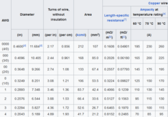
The bundle I purchased has 1AWG, wire table says 1/0AWG?

From the bus bars to battery rack: 12000/48*1.25 (safety factor)= ~313A
Wire table says larger than 4/0? Maybe my plan needs “adjusted”

I used 12000w thinking if both inverters were maxed out, but I hope I’m wrong. Thank you for any help/comments.
 
Okay, now I’m really confused. How can SS be selling packages where they are including wire that is too small (1AWG) to connect the inverter to the batteries?
Well, lots of snake-oil salesmen in the solar industry. Maybe they know their inverter can't really put out 6000W? Maybe they hope that the users never try to pull 6000W? Or maybe they just throw something together at the lowest price to skim by the safety margins?

Bottom line is "you get what you pay for"! The top, Tier-1 companies routinely underrate their products. The lower tier companies routinely overate their products.
 
Read the wire. Is there a brand, temperature rating, strand count, other markings? Look at the loose end and see if its very fine stranded? Is the sheath rubber like, silicone or vinyl?

These all matter when talking about ampacity of wire. That said, 1 awg welding wire 105c temp can carry 250 amps. Silicone wire can carry more. The chart you posted looks like one for standard THHN to me which is probably not what the wire is.
 
I am wanting to make sure my math for wire sizing is correct, sometimes I can get 1+1=3…
I have two 6000xp inverters and a rack of EG4 batteries.
My plan is to have a wire run with a fuse from the battery rack to bus bars (5’ long max) then run a separate wire run to each inverter (3’ long max)
From the inverters to the bus bars: 6000/48/.85= ~147A
The bundle I purchased has 1AWG, wire table says 1/0AWG?

From the bus bars to battery rack: 12000/48*1.25 (safety factor)= ~313A
Wire table says larger than 4/0? Maybe my plan needs “adjusted”

I used 12000w thinking if both inverters were maxed out, but I hope I’m wrong. Thank you for any help/comments.

The cables in the bundle appear to be this:

1710949917489.png

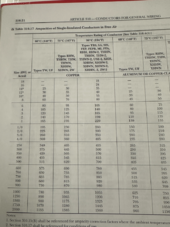
With each inverter having their own set of cables with inverter to bus connections, I believe the cable should be sized for 6000w. I typically size battery cables off of nominal voltage which in this case would be 6000/51.2 = 117 and times 1.25 for safety would be 146.48. From this I believe the 1 AWG would be safe based on the NEC Free Air Ampacity chart.

1710950054941.png
 
Specs for that type cable - looked it up - seems more than up to the task - pure copper high strand count - 105c rated - PVC sheath


Specifications:

Gauge Stranding Outside Diameter Weight LBS/ft
8 182 .270 in .054
6 266 .305 in .106
4 429 .350 in .160
2 676 .419 in .241
1 845 .490 in .315
1/0 1066 .530 in .391
2/0 1339 .579 in .478
4/0 2109 .695 in .735

For use as battery cables:
SAE J-378 Table of Allowable Amperage for conductors 50V or less with 105C rating
Gauge Amps Outside Amps Inside
AWG of Engine Space of Engine Space
8 80 68
6 120 102
4 160 136
2 210 178
1 245 208
1/0 285 242
2/0 330 280
4/0 445 378
 
Thank you all, I did look at the cables and indeed they do have the 105C rating. I found it interesting the difference the temperature rating can make in the allowable amperage and how many different rating tables there are for copper wire/cables.

Robbob2112, thank you for the link!
 
Back
Top