diy solar

diy solar

Chinese inverter discharges batteries without anything connected

SolarPowerUser2022

New Member
Joined
Aug 27, 2022
Messages
5
Hello,
I have a chinese MPS-V-PLUS inverter. It is similar to many other chinese inverters. It has a blue display and four buttons like ENTER, Up, Down and ESC. I don't have anything connected to the AC outlet but the battery gets discharged and recharged everyday. What could cause this issue? I'm using a LiFEPo4 48v 120Ah battery.

These are my settings which I changed after I did a Factory Reset:

Charger source priority (16):
CSO (Solar first)
Output source priority (01):
SbU (1. Solar 2. Battery 3. Utility)
Bulk charging voltage / C.V voltage (26):
56v
Maximum charging current (02):
30A
Maximum utility charging (11):
2A
Low DC cut-off voltage (29):
48v
Setting voltage point back to utility source when selecting "SbU" or "SOL" in program 01 (12):
51v
Setting voltage point back to battery source when selecting "SbU" or "SOL" in program 01 (13):
jetzt 54v
Float charging voltage (27):
jetzt 54.1v
AC input voltage range (03):
APL (90-280VAC)
Backlight Control (20):
LOF

Thank you very much!
 
Yes some of them use a stunning amount of power doing sweet fa. If you felt how warm it gets even sitting there staring at you?
 
There should be a switch to turn the inverter off so the inverter circuit will be off, the charge function will still be functioning.
 
There should be a switch to turn the inverter off so the inverter circuit will be off, the charge function will still be functioning.

And still pulling energy to support everything but the inverter. Your suggestion will lower the Tar load, but not eliminate it.
 
And still pulling energy to support everything but the inverter. Your suggestion will lower the Tar load, but not eliminate it.
It will be in less than 100mA, easy enough to verify if that is your concerned, I have two AIO and i turn my off, and the charger will still keeps the batteries charge up, OP is wasting power when no load connected to the AC output of the inverter.
You cannot eliminate the draw unless you want the SCC to be disconnected too, you cannot eliminate current draw from battery unless you disconnect every thing including the BMS.
 
Mines are PIP-1012LV-MS (2 years old now) and MK (about 1 year old now).
Edit: I just check the current draw just now, at night and inverter's switch are OFF, both units draw about 10mA!
 
Last edited:
Likely in 60-80 watt range for idle power. You can probably measure about 1.5 amps battery draw with no load on inverter with a clamp-on DC amp meter.

With a 120 AH battery you have about 3 days of no-load idling.
 
Hi!
I understand that these Chinese inverters (Voltronic, etc.) have higher idle consumption.
But what's not fully clear to me and where I ask myself if nobody so far tried to find a solution for, is:
The Axpert is configured SBU.
Grid is connected and always stable available.
When during the night Low Voltage Cuttoff gets triggered, I would expect that all the loads and the Axpert's self-consumption get drawn only from utility and that there is no further discharge of the battery at all.
But what I observe is that Axpert switches immediately to utility when LowVoltageCutOff gets triggered (you here some relay-klicking inside) and starts to supply the loads. So far everything as expected.
But there remains a residual ~70W discharge of the battery. And this is nasty because it drives my LiFePo-pack in Undervoltage-Switch-Off from which it can only be woken up via manual restart.
So does anybody know, what inside the Axpert is consuming these 70 amps from Battery even after LowVoltafe-CutOff and why these 70A are not pulled from utility?
Is there anything one can do against this?
 
Last edited:
Hi!
I understand that these Chinese inverters (Voltronic, etc.) have higher idle consumption.
But what's not fully clear to me and where I ask myself if nobody so far tried to find a solution for, is:
The Axpert is configured SBU.
Grid is connected and always stable available.
When during the night Low Voltage Cuttoff gets triggered, I would expect that all the loads and the Axpert's self-consumption get drawn only from utility and that there is no further discharge of the battery at all.
But what I observe is that Axpert switches immediately to utility when LowVoltageCutOff gets triggered (you here some relay-klicking inside) and starts to supply the loads. So far everything as expected.
But there remains a residual ~70A discharge of the battery. And this is nasty because it drives my LiFePo-pack in Undervoltage-Switch-Off from which it can only be woken up via manual restart.
So does anybody know, what inside the Axpert is consuming these 70 amps even after LowVoltafe-CutOff and why these 70A are not pulled from utility?
Is there anything one can do against this?
this has -0- to do with chinese inverters..
this is behavior of all electric equipment, and as an all in one contains more function, it will have more self consumption
 
Hi!
I understand that these Chinese inverters (Voltronic, etc.) have higher idle consumption.
But what's not fully clear to me and where I ask myself if nobody so far tried to find a solution for, is:
The Axpert is configured SBU.
Grid is connected and always stable available.
When during the night Low Voltage Cuttoff gets triggered, I would expect that all the loads and the Axpert's self-consumption get drawn only from utility and that there is no further discharge of the battery at all.
But what I observe is that Axpert switches immediately to utility when LowVoltageCutOff gets triggered (you here some relay-klicking inside) and starts to supply the loads. So far everything as expected.
But there remains a residual ~70A discharge of the battery. And this is nasty because it drives my LiFePo-pack in Undervoltage-Switch-Off from which it can only be woken up via manual restart.
So does anybody know, what inside the Axpert is consuming these 70 amps even after LowVoltafe-CutOff and why these 70A are not pulled from utility?
Is there anything one can do against this?
How do you see or measure that 70A still being drawn from the battery when the unit is in the Low Voltage shutdown and switched to utility mode which at that point the utility should be charging the battery until the battery Voltage reaches the 'Back to battery source' set point?
 
I see it from my JBD-BMS monitoring and I can measure it on the Battery cables w/ Clamp-Meter (approx. 1.5A).
 
I see it from my JBD-BMS monitoring and I can measure it on the Battery cables w/ Clamp-Meter (approx. 1.5A).
'But there remains a residual ~70A discharge of the battery.'
So where did you see the 70A draw?
 
I see it from my JBD-BMS monitoring and I can measure it on the Battery cables w/ Clamp-Meter (approx. 1.5A).
I think you mean 70w draw. 1.5a X 48v = 72w

Yes there is draw on the battery from the AIO so long as it is connected to battery. I ran a test on my EAsun spare unit last night running in Eco, or low power mode, and confirmed the ~50w that the operations manual lists as spec.

When pondering design of an AIO and the practicalities of how to run power free, or a bare minimum, you encounter issues of power interruption. Switching AC is fairly easy but DC is not due to arc protection.
 
I'm so sorry this was a typo! I corrected my post! Please excuse me!
I see a residual discharge of 70W on the BMS, which equivalents to 1.5A I measure on the battery cables.
And to make it a little bit more clear.
It's not a problem that the Axpert has an idle consumption of ~70W ... this is the price I'm willing to pay for cheaper all-in-one.
But the problem is, that it draws these 70W from Battery even after LowVoltageCutOff kicked in, where it should draw it from grid.
No method to draw from grid unless you charge from grid. AIO would need to convert AC to DC.

ETA: These units run on DC and when you think about it that is necessary because they are off grid capable.
 
Light bulb moment.

There is a way that this could be solved if the AIO manufacturers incorporated it. At battery low voltage set point instead of going into shutdown the unit could check for AC power and engage DC charging at a low amperage enough to maintain AIO operation and above battery low voltage cutoff. Note: this is different than using set amperage charging while in AC pass through. (many do not want to charge from AC so operate in PV only charge mode). It would pass off AIO's power needs to the AC side until PV charging had raised battery voltage sufficient enough to go out of AC Bypass.
 
Good light bulb, but I'm not aware that Voltronic Axpert is possible to do this.
But I have a very similar plan to overcome this!
Using "Charge Source Priority Timer" to change from " Solar only" to "Solar & Utility" for 1-2 hours (don't know if Axpert Timer allows 1h ... discussed in another thread) and by this allow the battery to get charged with current from grid to compensate for the "idle current".
If set properly, this extra computational charge will hopefully keep my Battery from triggering low voltage shut down.
 
The inverter should shut down when it reaches low battery cutoff. It will still draw some power to run microcontroller and display but it should be a small amount of power.

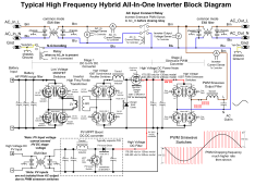
When AC input is present, cheap AIO HF inverters can do slightly different things depending on particular model and user settings. Cheap HF inverters have trouble switching between charging battery and supplying AC output from inverter. They need about 30-100 msecs to make the switchover which results in inverter dropping out for that time period.

On cheap HF inverters, when AC input is present, the AC input is just passed through to AC output and inverter circuitry is locked into battery charging mode tapping power from AC input. If solar is present, and depending on user setup priority, the PV power goes to supplementing AC output and/or battery charging.

Some really cheap AIO inverters have to dedicate the AC output PWM sinewave generation circuitry to either charging battery or supplementing AC output from solar power when AC input is present. You can have PV supply one or the other but not battery charging and AC output supplementing at the same time. This is because it uses the AC output PWM H-bridge to regulate charging preventing its use for sinewave output generation to supplement AC output from PV power. Units that allow simultaneous charging and AC output supplementing have an extra buck switcher IGBT or MOSFET switcher and diode in the battery to HV DC converter path. This is the more common configuration.

Just about all hybrid inverters these days have a small AC input power supply that will power the microcontroller and display from AC input if present, otherwise power is supplied from battery or PV power. Since PV controller takes some overhead power, it comes from battery source so if low battery is tripped it may also shut down PV controller. This is a 'catch22' as battery is low on charge, PV power is available to provide charging, but because of low battery it does not allow PV controller to operate.

Some models will run PV charge controller from PV power if there is enough PV power available. This is a little trickier for PV charge controller as it may get stuck in a startup-shutdown recycling when available PV power is marginal.

HF inverter block diagram.png
 
Last edited:
Light bulb moment.

There is a way that this could be solved if the AIO manufacturers incorporated it. At battery low voltage set point instead of going into shutdown the unit could check for AC power and engage DC charging at a low amperage enough to maintain AIO operation and above battery low voltage cutoff. Note: this is different than using set amperage charging while in AC pass through. (many do not want to charge from AC so operate in PV only charge mode). It would pass off AIO's power needs to the AC side until PV charging had raised battery voltage sufficient enough to go out of AC Bypass.
This is how my MPP solar units work
 
...

When AC input is present, cheap AIO HF inverters can do slightly different things depending on particular model and user settings. Cheap HF inverters have trouble switching between charging battery and supplying AC output from inverter. They need about 30-100 msecs to make the switchover which results in inverter dropping out for that time period.

On cheap HF inverters, when AC input is present, the AC input is just passed through to AC output and inverter circuitry is locked into battery charging mode tapping power from AC input. If solar is present, and depending on user setup priority, the PV power goes to supplementing AC output and/or battery charging.


...
Typically the user sets charging mode to be from PV only. So at battery transfer to utility setpoint the unit goes into AC pass through but no charging occurs. This is the point that the batteries will eventually get drained because either they are insufficient to carry idle load through night or a person experiences bad weather for PV charging.

That is where my solution comes into play. The unit can charge when in AC bypass but the user has it set for no charge. Battery low voltage set point is reached. The unit engages a minimal charge current. It does not require a massive rethinking of AIO design. It is simply a programing change.
 

diy solar

diy solar
Back
Top