diy solar

diy solar

Combining two separate strings in the attic for a single homerun, what's needed?

UpWithSolar

New Member
Joined
Jun 30, 2024
Messages
2
Location
USA - California
Hello,

Question about combining strings:

System: All 385W panels with IQ8+ microinverters. Roof mounted panels, one group of 4, and one group of 9.

I will be combining panel strings from two different areas of the roof (see attached drawing). The combining will occur in the attic.

My plan is to run the wiring into a “junction box” in the attic, the have the combined 13 panel string homerun to the Enphase Envoy box.

For this junction box (green in the drawing) initially I was thinking I could just join the wires as if they were still in a single array on the roof. But in reading up on it, it would appear that I have to use a String Combiner Box with Fuses? Is this right? (keeping in mind all the panels are identical).

Additionally, I see that most combiner boxes have the MC4 connectors integrated - so do I switch back to those if I do use a Combiner Box? My plan is to switch from Enphase wire on the roof to 10ga THWN-2, so that's what I will have when it it hits the junction box in the attic...

I guess my biggest question is, do I need the box fused?

Thanks for advising, best regards...
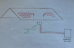
Screen Shot 2024-06-30 at 2.54.15 PM.png
 
Since you have microinverters, you are only dealing with an AC circuit.
Standard AC wiring rules apply. So a junction box is fine.
 
Hello,

Question about combining strings:

System: All 385W panels with IQ8+ microinverters. Roof mounted panels, one group of 4, and one group of 9.

I will be combining panel strings from two different areas of the roof (see attached drawing). The combining will occur in the attic.

My plan is to run the wiring into a “junction box” in the attic, the have the combined 13 panel string homerun to the Enphase Envoy box.

For this junction box (green in the drawing) initially I was thinking I could just join the wires as if they were still in a single array on the roof. But in reading up on it, it would appear that I have to use a String Combiner Box with Fuses? Is this right? (keeping in mind all the panels are identical).

Additionally, I see that most combiner boxes have the MC4 connectors integrated - so do I switch back to those if I do use a Combiner Box? My plan is to switch from Enphase wire on the roof to 10ga THWN-2, so that's what I will have when it it hits the junction box in the attic...

I guess my biggest question is, do I need the box fused?

Thanks for advising, best regards...

I am very confused. What's the starting state and end state of the system? You are missing multiple key points in your project writeup.

If you are using microinverters typically you use AC trunk cable (of the type provided by the manufacturer) into a junction box. After that, it is spliced to any 240V wiring method you want.

#10 THWN2 is also weird for Enphase. Enphase trunks are always 12A or 14A last I checked.

 
I am very confused. What's the starting state and end state of the system? You are missing multiple key points in your project writeup.

The project is, of course, more detailed - but I wanted to keep my question short and on point regarding the combining of the strings between two separate groups of PV panels and the Envoy Combiner box . What other information would be helpful?

If you are using microinverters typically you use AC trunk cable (of the type provided by the manufacturer) into a junction box. After that, it is spliced to any 240V wiring method you want.

Yes, this was what I said in my original post. Perhaps I wasn't clear (it's only my second PV project). My microinverters will be linked using Enphase Q cable. The Q cable will then transition (on the roof) to 10awg in an Enphase J-box (rail mounted). The 10awg then goes from the Jaybox through the roof via EMT conduit into the attic and it's 10awg all the way to the Envoy box.

#10 THWN2 is also weird for Enphase. Enphase trunks are always 12A or 14A last I checked.

Curious why this is weird (the system was designed by an engineer, who seems very sharp and is experienced with PV system design). As far as I know, Q Cable is 12 gauge so I would be surprised to see that transitioned to 14awg anywhere downstream, but maybe you can? As for 10awg, I assumed it is because of the homerun distance to the Envoy box.
 
The project is, of course, more detailed - but I wanted to keep my question short and on point regarding the combining of the strings between two separate groups of PV panels and the Envoy Combiner box . What other information would be helpful?

OK, your project makes sense now. The original one sounded a bit like ChatGPT copypasta with the odd project description, with the reference to MC4 combiners (DC only) and #10 THHN (usually people don't upsize).

What you provided here as details were OK.
For this junction box (green in the drawing) initially I was thinking I could just join the wires as if they were still in a single array on the roof. But in reading up on it, it would appear that I have to use a String Combiner Box with Fuses? Is this right? (keeping in mind all the panels are identical).

Yes, this was what I said in my original post. Perhaps I wasn't clear (it's only my second PV project). My microinverters will be linked using Enphase Q cable. The Q cable will then transition (on the roof) to 10awg in an Enphase J-box (rail mounted). The 10awg then goes from the Jaybox through the roof via EMT conduit into the attic and it's 10awg all the way to the Envoy box.
You can splice with a regular Junction box in the attic (ie 4" or 4 11/16" box). I did that for my string. Though note that you COULD run into trouble with the fact that sometimes the microinverter installation manual show the string as a chain, while when you combine like this the circuit topology is different.

For a regular load branch circuit you don't need extra fusing when you splice in a junction box.

For a branch circuit with power sources things are more complicated, and for feeders you have to do a more complex calculation (per 705.12). This is a branch circuit though.

Overall, I think what you want to do is fine. I did my Microinverters -> rooftop combiners with the branching circuit topology with no fusing, and without worrying about there not being specific dispensation in the install manual to do this. And I couldn't come up with a reason for why it was unsafe. But, this was not the wiring that my line diagram showed.

NEC may require you to increase to EGC to #10 because you are upsizing the current carrying conductors, and there are rules around upsizing EGC in some of those conditions.

You don't need to use THHN & conduit for AC strings, most people don't. (I did for my own house, but that was to exceed code minimum. And I only used #10 THHN because of my use of Hoymiles microinverters, which have 30A branch circuit limit compared to the 20A branch circuit limit of Enphase).

Curious why this is weird (the system was designed by an engineer, who seems very sharp and is experienced with PV system design). As far as I know, Q Cable is 12 gauge so I would be surprised to see that transitioned to 14awg anywhere downstream, but maybe you can? As for 10awg, I assumed it is because of the homerun distance to the Envoy box.
If you have high solar production then the efficiency benefit might be worth it. Also, if you're already going platinum plated with using conduit, the materials cost and labor cost difference between #12 and #10 THHN are proportionately pretty small.
 
NEC may require you to increase to EGC to #10 because you are upsizing the current carrying conductors, and there are rules around upsizing EGC in some of those conditions.
Only when code required the upsizing. Not when you just do it to feel better.
 
Only when code required the upsizing. Not when you just do it to feel better.
I think it depends on code revision. First hit on Google says it covers any size increase (250.122)

(B)Increased in Size. Where ungrounded conductors are increased in size from the minimum size that has sufficient ampacity for the intended installation, wire-type equipment grounding conductors, where installed, shall be increased in size proportionately, according to the circular mil area of the ungrounded conductors.
It only applies when you increase per code.
This is because the same things that affect the current carrying conductors, also affect the EGC's ability to carry sufficient current.
 
What you say makes sense, but this analysis disagrees, and the way I parse the 2017 and 2020 english disagree too.


I checked 2023 and it's identical language to 2020.

(IMO it's a 💩 show)
 
What you say makes sense, but this analysis disagrees, and the way I parse the 2017 and 2020 english disagree too.


I checked 2023 and it's identical language to 2020.

(IMO it's a 💩 show)
The words "any other reason" are referring to other parts of the code.
The code gives minimum requirements.
It doesn't cover the installers whims.
 

diy solar

diy solar
Back
Top