A couple of things or more - was this permitted and inspected? I don't care but can make a difference in answers
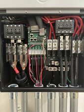
- Each battery needs a fuse or breaker between the positive pole and the bus bar. If they have built in breakers that is great. Looking online there is only a small switch per battery with no mention of fuse or breaker. What this means is that if there is a fault in one battery that is a short from a failed BMS the other 9 will dump 100 amps each into the failed pack. This would cause the 4 awg wire to immediately flash to several hundred C in a fraction of a second. 900amps will do that to you. I dunno how the battery would hold up to that but I wouldn't want to find out. If I were you I would immediately purchase 10 class T fuses 125amps each and holders and install them at the bus bar and connect your 4 awg wires to them. They are, 30cm long 4awg included with the rack.
- The connector looks like an Anderson SB350, max current 450amps. Assuming the wire is welding wire in a rubber like sheath it can carry 440amps using the windy nation welding wire charts. So this checks.
- There should be a 500 amp class T JJLN fuse inside the battery cage where the positive wire of the anderson connectors is attached in a fuse block with cover. This is 400amps +20%, nearest size. Without this fuse a short along the battery cables to where they enter the raceway would cause the 1000 amps to melt the sheath to melt the sheath in 5 second and then the real issue happens. The problem is a 400amp breaker would trip in around 5 seconds. But, 2 x 200amp breakers
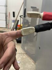
- That Y connector from the two double lug 200amp connectors is just wrong. It can be done as a bus bar so long as it is at least a quarter inch thick. But my real problem with it is the contact patch. It should be a double lug where the 4/0 cable attaches if you want to fudge it, but in reality it should be the lug I am posting at the end. Seems like someone cut corners.
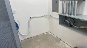
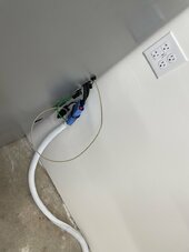
The NEC rule says that DC lines like this MUST be in metal conduit when in or on a dwelling. The state can add rules to go stricter but not take them out or reduce them. My other major problem is where the NEC states the conductors must be protected from harm. This usually means inside conduit or inside a metal raceway. It doesn't mean a white sock attached to the wall. Inside LFMC, rigid, EMT, or a raceway. The NEC does say the DC wiring can't be in the same conduit or raceway as the AC wiring so that is another problem from the look of it.
Where they might have gotten not in conduit is the rule for dc wire under 50v not being required to be in conduit. Problem is the battery voltage is 51.2v. Older lower voltage systems didn't need it and new stuff does.
If this was installed without a permit I would suspect the installers of falsehoods. And if it was inspected the inspector was not doing his job.