diy solar

diy solar

DC Circuit Breaker for Hybrid Inverter

hgg

New Member
Joined
Sep 5, 2022
Messages
41
Hi,

I just found out that DC circuit breakers not only have polarity but current flow direction as well...
I recently bought the TOMZN TOB1Z-125 C100 125A circuit breaker because I wanted to connect it
between the battery, 24V 100Ah and the hybrid inverter MPPSolar PIP-2424MSE1.

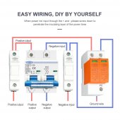
If you have a look at the connection diagram of the DC breaker, you will see that positive goes
to the left and negative to the right. Not only that, but input is at the top and output from the
bottom side.

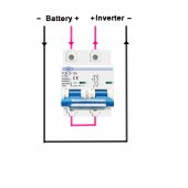
The problem is that the current direction between the inverter and the battery is bi-directional.
The battery will both be charged and supply current as well.

It looks like that the particular DC breaker is not compatible with my setup.
Correct?

If this is the case, are there any bi-directional (load/line) DC breakers that you can suggest?
Thank you.
 

Attachments

  • Tomz Breaker Polarity and current flow.jpg
    Tomz Breaker Polarity and current flow.jpg
    126.7 KB · Views: 108
Fuses offer bi-directional protection and can be withdrawn and used as points of isolation once there is no load current flowing.
A polarized DC MCB cannot be used to even break load current in an application where current can flow in either direction wired as shown.
So it is unsuitable for your purpose when wired as shown.
However, if 1 leg, say the "+" was wired the right way and looped back to also the wrong way through the MCB then a polarized MCB should break the current regardless of the current direction.
 
Yes all DC breakers are directional and not so suited to use between an inverter and battery, but it's about the best we have for now.
It is made directional because they want the least moving parts connected to the current supplying fault. If you look at the diagram on the breaker, you can see the "line" is connected to fixed studs and the 'load" is connected to the trip arm.
Good breakers have 2 trip mechanisms, a slow thermal bi-metalic strip and a quick magnetic trip.
It is this quick magnetic trip that needs to be different between AC and DC breakers as well as the DC breaker needing a larger gap and quicker acting contact points.
AC has no current flow during the cycle so the arc will break, not so with DC.
 
  • Like
Reactions: hgg
"A polarized DC MCB cannot be used to even break load current in an application where current can flow in either direction wired as shown."

Why is that ??

@Quattrohead So, can I use it wired as shown in the diagram?
(Input will be the battery and output the inverter.)
 
@Phil.g00 "A polarized DC MCB cannot be used to even break load current in an application where current can flow in either direction wired as shown"

Is that because of arcing when trying to break the circuit under load?

"However, if 1 leg, say the "+" was wired the right way and looped back to also the wrong way through the MCB then a polarized MCB should break the current regardless of the current direction"

So do you mean that it can be used to break only one conductor? (the positive)
(I wouldn't mind that actually)
 
"A polarized DC MCB cannot be used to even break load current in an application where current can flow in either direction wired as shown."

Why is that ??
A polarized MCN contains permanent magnets. As you know like poles repel. In a nutshell, the DC arc current also represents a magnet.
If it is a like pole it is repelled into plates which stretch it longer until the arc breaks and is extinguished.
If the DC arc current is in the wrong direction it is now a magnet that attracts so it isn't repelled and doesn't get extinguished causing a catastrophic failure of the MCB.

A polarized MCB wired as shown will fail in a bi-directional current application.
 
So do you mean that it can be used to break only one conductor? (the positive)
(I wouldn't mind that actually)
Yes, what I am saying is that one magnet will always be correctly orientated to break the arc regardless of the current direction.
The caveat is that the voltage rating of the MCB ( which usually has two breaks) should be at least twice the circuit voltage.
So that one break can still withstand the circuit voltage.

I would still prove this under controlled conditions during commissioning for my own piece of mind.
 
The bi-metalic part will still save the day, but s l o w l y.
DC breakers are not perfect but still way better than nothing.
 
The voltage rating of this MCB is 600V and I will only use 28V max between the inverter and the battery.
So its better to use it to break only the positive, correct?
 
@Phil.g00 "A polarized DC MCB cannot be used to even break load current in an application where current can flow in either direction wired as shown"

Is that because of arcing when trying to break the circuit under load?
Yes it can, it is being used as a switch NOT under fault load conditions.
 
The voltage rating of this MCB is 600V and I will only use 28V max between the inverter and the battery.
So its better to use it to break only the positive, correct?
Yes, you have ample voltage capability.
Technically, so long as the wiring is adjusted accordingly it doesn't matter which leg the break is in.
From a conventional point of view, the break will be expected in the positive leg.
 
Wow, I wouldn't want something like that in my house... ?
Absolutely not.
But we don't know the voltage involved, actual specifications of that breaker and it was deliberately wired wrong.
Yes it does show a valid concern.

Anyway, bottom line is a CB is better than nothing but not perfect.
 
So, will the following wiring be a safe configuration for my setup and the specific
DC breaker? (hybrid inverter + battery = bidirectional current path)
 

Attachments

  • Tomz Diagram.jpg
    Tomz Diagram.jpg
    69.5 KB · Views: 67
No, you are still giving it conventional current directions.
Take it out of the bottom left pole terminal and loop it into the top right pole terminal.
 
  • Like
Reactions: hgg
Back
Top