diy solar

diy solar

Circuit breaker

slowbutsure

New Member
Joined
Apr 21, 2022
Messages
189
Hi,

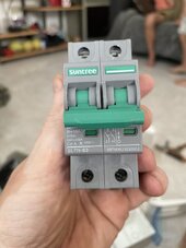
I’m wiring a string to a circuit breaker. Looking at the breaker I have I want to double check I’m wiring it correctly.

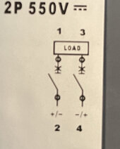
The diagram seems to be Saying:

Input from panels =. Live 1 and neutral 2

Output to inverter = Live 3 and neutral 4

Can anyone confirm I’m reading that right?

Thanks.
 

Attachments

  • 000D23B7-006A-4068-8EA8-19A194E6480D.jpeg
    000D23B7-006A-4068-8EA8-19A194E6480D.jpeg
    98.5 KB · Views: 25
  • 77C0CC49-B0BC-4A81-B2E2-A3A283009597.jpeg
    77C0CC49-B0BC-4A81-B2E2-A3A283009597.jpeg
    107.4 KB · Views: 25
You really don't want to do that. While you're reading it right, that breaker is a double pole and designed to break both legs of a single circuit so you could break the positive and negative of your panels, or the positive and negative if your SCC, but if you wanted to disconnect your panels you'd end up cutting power from the batteries that the SCC needs to operate and both would be turned on at the same time which is a bad idea.
 
You really don't want to do that. While you're reading it right, that breaker is a double pole and designed to break both legs of a single circuit so you could break the positive and negative of your panels, or the positive and negative if your SCC, but if you wanted to disconnect your panels you'd end up cutting power from the batteries that the SCC needs to operate and both would be turned on at the same time which is a bad idea.

Could you break that down for me a bit? Thanks.
 
Since you mention panels in your post I will guess that your string is PV panels and you are intending the breaker to disconnect their input to your SCC (or AIO's SCC input). So yes the you have positve and negative from the panels (Note: There is no Neutral!) coming in from the panel at the top of the breaker and going out to the SCC at the bottom (Line to Load). Their is no polarity markings on your breaker so it seems to not be a concern which lead goes to which breaker pole. (So 1 and 2 can be pos and 3 and 4 can be neg. )
 
The diagram does show polarity markings in a sense.. or at least it implies it doesnt matter which side is positive or negative as long as the source ends up on 2&4 and the load ends up on 1&3.
 
The diagram does show polarity markings in a sense.. or at least it implies it doesnt matter which side is positive or negative as long as the source ends up on 2&4 and the load ends up on 1&3.
That’s helpful, thanks. May sound stupid but I’m struggling to see which end is 2&4 and which end is 1&3. Can you shed any light on that?
 

Attachments

  • 5E7CC294-7F31-49B4-AD1D-31303E6762D5.jpeg
    5E7CC294-7F31-49B4-AD1D-31303E6762D5.jpeg
    98.5 KB · Views: 8
According to the diagram on your breaker.
1 = top left
2 = bottom left
3 = top right
4 = bottom right


As holding the breaker in your hand, Power Source, goes on the top two terminals 1 & 3 on the breaker.
Connected Load connects to the bottom of the breaker. Terminals 2 & 4.

Beats me why the diagram on the right shows the load on the top of the breaker.

With the breaker handle in the off position the knives of the breaker should be de-energized.

Source, Line, on top.
Connected Load out, on bottom of breaker.

.
 
Usually, yes.
But I can't recommend going against the manufacturers instructions.
Agree. It would be nice to know the manufacturer's wiring application for the drawing though.
If I only had the breaker, and not the drawing, I would wire the Line power on top and load on the bottom. (Bottom being with the breaker handle in the off/open position.
Usually if a breaker is used/wired as the drawing shows it is used to back feed the bus of a main lug only electrical panel for an example.
Hard to know what the reason is.
That's a din rail breaker. They have many different designs for many different situations. I can only assume that there is a situation that requires that configuration. Or they wouldn't have designed it that way.
Customers special order all kinds of products. And the extras end up on the open market.
 
Back
Top