diy solar

diy solar

Redundant Circuit Breaker?

PaulLad

New Member
Joined
Jul 14, 2020
Messages
169
I'm using the design in this pic as a model. But I don't really see the value in having a circuit breaker between the CC and the fuse. Seems redundant to me. Am I right? Thanks!
 

Attachments

  • website-design-solar-system-2_orig.jpg
    website-design-solar-system-2_orig.jpg
    214 KB · Views: 40
It fits the definition of redundant. Yup.

But two things…
-With the circuit breaker it would be the only disconnect so it has function for convenience or servicing.
-With LiFePo4 batteries the ClassT fuses you should are fairly expensive. So in a fault like a ‘surge’ (nuisance blow) that’s not causing a sudden catastrophic battery discharge the CB - depending on rating - would trip saving a $40+ fuse. Yet you’d still have the safety of the 10k-amp tolerance of the ClassT
 
A circuit breaker and a fuse perform 2 very different functions. That is why both are placed in line to protect the components and wiring. A fuse blows very rapidly (even if labeled slow blowing as opposed to fast blowing) in response to an over current and protects hardware. A circuit breaker opens very slowly. They are usually rated as type A,B,C and D. A breaker opens in response to a high current over a specified period of time. The overcurrent results in a heat buildup in the wire which can melt the insulation resulting in an electrical arcing and a fire. No good if the wire is in a conduit inside a wall or near combustibles or where people and pets reside.
 
The way you have it wired is that the Circuit Breaker only functions with the charge controller. Power to the inverter only travels through the Fuse.

Assuming you put the breaker between the battery and the fuse, then it would function as a disconnect, and possible trip faster than the fuse. If your main fuse was a Class T, then the Class T can pass 2x amps for 1 hour before blowing. The Breaker would trip at 1x. The fuse would then be a backup to the breaker, especially if there was a short that exceed the rating of the breaker (breaker held closed by the current).
 
As said above the fuse is not in line with the breaker, and I would do it as Reed said, but I just added that most of those types of breakers are fake, or they don't always work properly, also, if that's the bus bar I think it is, it's made of brass and is rated for just 20-30a between fasteners, I would try and buy ones made of copper.
 
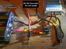
With longer wire to battery, SCC and inverter branching close to each other, the voltage drop/increase they create over length of wire can impact behavior. People have see one or the other shutting off or charge phase changing, I think. (maybe positive battery cable will be fairly short, can't tell.)

SCC and inverter connected might have been more of an issue for lead-acid than lithium? Ideally you have a fuse for catastrophic shorts right at the battery, then a busbar, then maybe a cable direct to inverter and a fuse or breaker to SCC.

But it may work OK as you have it.

Stacking ring terminals, I would put higher current battery against busbar, lower current SCC on top.
I would put battery and inverter adjacent, or even stacked. Rather than current going length of busbar.
I would put SCC terminal on opposite side of battery terminal from inverter, so it doesn't see voltage drop across busbar.

(If two battery cables or two inverter cables and one of the other, I put the single cable towards middle of busbar and the two on either side. So half current goes through busbar cross section.)
 
Oh, forgot you were playing toy sized inverters ?
Most of us have to use 2/0 battery cable, not 14 awg.
And your AC is just 2 or 4 amps.

The inverter in photo looks like more watts.
 
I think we are all jealous, as I can only dream of needing a 500w inverter :)
I have a 300W Giandel I keep in the jeep for cordless tool battery charging or to run a soldering iron. I think it was around $50 and I needed it?
 
Back
Top