diy solar

diy solar

DC Direct EV charger - DIY Build

jakepusateri

100K Ohm Resistor
Joined
Apr 21, 2023
Messages
28
Location
Indiana
I want to build a DC direct EV charger. Not because it's practical, but because I think it'd be fun. I know people are working on commercial versions, but there's no fun in waiting around, and they all want to lock you in to their ecosystem.

Other reasons include off-grid resilience and better efficiency by not going DC->AC->DC. Or imagine an EV charging station in the middle of some area that you can't run big power to. Panels are getting cheaper by the day. Or even bringing your solar panels with you like the guy doing a solar cannonball right now (or The Martian).

Here's the high-level plan:
Power board - High voltage synchronous buck/boost MPPT charge controller (e.g. 500v, 30a). This will make it very efficient to convert to the ~400V of most EVs (like my Model Y). I haven't found anything like this that exists voltage-wise, so will be designing my own, mostly following the several existing designs and sourcing components rated for the higher voltages.
Control board - Pi CM4 running Everest open source EV charger software. This will handle speaking CCS to the car and high-level communication like wifi and data logging.
The boards will talk over some protocol, tbd between CAN, SPI, MOD, I2C. This will help the power board focus on being safe and not blowing things up or starting fires with up to 15kW of power since there's a full embedded linux on the other board, and a RTOS linux is not.

Optional Features that should be possible but are not immediate focus:
- passthrough to normal inverter when not charging car
- bidirectional from car (though this should work going to the mppt input of an existing inverter, like my 18kPV)

I've done a bunch of research in the past month and the idea just won't leave my brain. I took a few hardware classes in college, but I'm mostly a software guy. Anyone who wants to help would be appreciated. I'm planning on making the whole thing open source, and I'll try to keep this thread updated as well.
 
The problem is IMO push vs pull.
A conventional charger (DC or AC) wants to be told how much it can draw (pull) from the connector that is feeding it.
Eg: AC EVSE tells with a PWM signal how much max can be pulled from the grid.
Long time ago I was involved with a DIY Chademo setup and I studied the protocol, but have since forgotten the most of it (luckily!)
With PV you don't know how much energy you have available and it can change rapidly.
That is why IMO currently the only way to do it is convert everything from DC -> AC (grid == ever wanting battery you can charge) and by measuring how much surplus energy you are putting in the grid, you can direct an EVSE how much to pull and basically keeping the grid at zero.
That is how I do it currently with an interface with my smart meter (HAN device) , some python code and an openevse L2 AC to my EV.

I too would love to have DC -> DC directly but a panel will not tell you have much energy is available until you find the MPPT curve.
And EV's are simply not made for that. That leaves putting PV DC -> battery DC (HV) and from there instruct your EV (L3) to take a certain max amount of energy from the battery. That protocol should be multiple times per second so could be adjusted fairly quick.
The battery storage capacity could be fairly small as well imo, the intention is not to use stored battery, but load the PV with the mppt curve and while charging the battery to instruct the EV to take away the same amount of energy == not charging the battery.

Just my $0.02
 
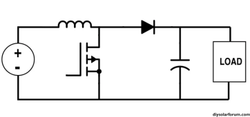
I would do simple boost converter. Synchronous converter will be bidirectional and allow power to flow back to panels in case you mess up your PWM. Boost converter with diode will block current from going back to panels and compensate for shaded panels in series string by boosting voltage unlike buck converter.
boost.PNG
 
With DC charging you will need to provide how much amps available, 20 times a sec at least.
Depending on SOC, temp etc the EV might be pulling less.
The Chademo protocol I studied, the EV tells the DC charger exactly how much volts it wants at the connector. You have to regulate that very precisely, not just have a higher voltage than the battery and hope it will charge.
 
I would do simple boost converter. Synchronous converter will be bidirectional and allow power to flow back to panels in case you mess up your PWM. Boost converter with diode will block current from going back to panels and compensate for shaded panels in series string by boosting voltage unlike buck converter.
View attachment 178059

@AntronX I've looked at the asynchronous variant before, but for the 80V open-source designs it seemed like the diode voltage drop would cause much lower efficiencies. And for this project, efficiency is the name of the game, otherwise we'd just convert to AC. I will admit that the operation and programming would be simpler for the asynchronous one, and because we'll be using a much higher voltage, the percentage power loss should be a lot smaller. Maybe V1 could use that method, and focus on efficiency once I have a working version.
 
With DC charging you will need to provide how much amps available, 20 times a sec at least.
Depending on SOC, temp etc the EV might be pulling less.
The Chademo protocol I studied, the EV tells the DC charger exactly how much volts it wants at the connector. You have to regulate that very precisely, not just have a higher voltage than the battery and hope it will charge.
Once you get past the communications protocol and open up the relays, an EV battery is just a battery. The only real control an MPPT can have is adjusting the PWM to load the panels and provide max power for the given conditions, be that in constant current mode or constant voltage mode of the charger, and that'll be in the tens of khz range. The CCS comms will give you a voltage and amperage target, and more exact will be better, but the battery itself will set the voltage.
 
@AntronX I've looked at the asynchronous variant before, but for the 80V open-source designs it seemed like the diode voltage drop would cause much lower efficiencies. And for this project, efficiency is the name of the game, otherwise we'd just convert to AC. I will admit that the operation and programming would be simpler for the asynchronous one, and because we'll be using a much higher voltage, the percentage power loss should be a lot smaller. Maybe V1 could use that method, and focus on efficiency once I have a working version.

Don't understand why the diode would cause much lower efficiencies. Diode drop might be 0.7V.

0.7V/80V = 0.9 %

In the grand picture, that's not much of a loss.
 
650v 20A SiC diode will have 1.1V forward drop in 250v 10A to 370V 6.7A step up converter. That's a conduction loss of 11W or 0.44%. Switching loss is negligible. With careful design you can achieve ~98.5% efficient boost converter. Edit: I forgot to factor in 70% duty cycle for the diode. This makes average conduction loss just 7.7W.
 
Last edited:
Is it wise to use a boost converter? No concerns for ground isolation? I would use a push-pull pwm converter.
 
If panels are floating then it should be no problem but If there is ground leakage it could trip the HV to body leakage detector in the car and generate a DTC. If panels are simultaneously connected to non isolated inverter then it could be a problem i think. Inserting HF isolation transformer in place of boost inductor would drop total efficiency by about 1 - 2% due to magnetic coupling loss. Example: Flyback converter.
 
Last edited:
I have a question: My EV6 charges at up to 800 volts DC and I have reached speeds of up to 264 kW at fast chargers. How exactly do you plan on generating this kind of voltage and amperage as well as communicate with my battery pack safely?
 
My EV6 charges at up to 800 volts DC
Your Ionic 6 also charges at 400Vdc. But hes only talking about 30A level, not 300A. Comms can be done over CCS protocol. Edit: Tritium is doing DC powered user terminals fed by central AC-DC converter unit. It should be possible to tie in DC solar arrays directly into that 950Vdc bus.
 
Last edited:
Hell, theoretically you could take that Tritium user terminal and connect it direct to 1000V solar arrays. Software in the dc converter would have to be modified to support MPPT but it can be done. This would make fully offgrid batteryless solution. With added PV ground isolation monitoring there would be no need for converter dc isolation.
 
Last edited:
I have a question: My EV6 charges at up to 800 volts DC and I have reached speeds of up to 264 kW at fast chargers. How exactly do you plan on generating this kind of voltage and amperage as well as communicate with my battery pack safely?
DC charging can go as low of amperage as you feel like. This test charger speaks CCS and charges at about 1mA and is powered from a portable battery bank.

 
DC charging can go as low of amperage as you feel like. This test charger speaks CCS and charges at about 1mA and is powered from a portable battery bank.

Can you post a link of the data that doesn't require a login/account ?
Very much interested
 
DC charging can go as low of amperage as you feel like. This test charger speaks CCS and charges at about 1mA and is powered from a portable battery bank.

Can you print to PDF and upload here? Article behind login wall.
 
I would do simple boost converter. Synchronous converter will be bidirectional and allow power to flow back to panels in case you mess up your PWM. Boost converter with diode will block current from going back to panels and compensate for shaded panels in series string by boosting voltage unlike buck converter.
View attachment 178059

I don't believe a boost regulator will work. It's usually used for low power outputs. The voltage gain (Vo/Vin) is limited by the resistance ratio of the inductor and the load (R_L / R_LOAD). What does the OP have in mind for solar voltage (Vmp)?

Boost converter limits

For a max gain of 9, inductor resistance needs to be 300 times lower than load resistance. Load resistance in this case is a lithium battery, right?
 
You guys do know that several companies already make PV systems with hybrid inverters that direct the PV into the EV DC charger right?
 
What does the OP have in mind for solar voltage (Vmp)?
500V 30A input. That would call for buck converter which would work just fine. I was suggesting 250V to 370V boost which also works with voltage gain of only 1.5. At 7A battery charge current boost converter output sees 52 ohm impedance and DC resistance of inductor would be under 1 ohm. Article you linked refers to very high in/out voltage ratios not applicable here.
 
Back
Top