diy solar

diy solar

Developing own BMS

ramiws

New Member
Joined
Aug 1, 2020
Messages
91
Hi!

I am happy that I have joined the forum, I have been reading around and posted few questions. Very nice and friendly people!

I am building my own off-grid cottage. I have good software background and I am planning to develop my own BMS ( I will happily share it when it is working)
I have been reading info about all the different BMS out there, so I just need you to correct me if I am wrong about those assumptions:
A BMS task is:
-Cut the consumption when one or more of the cells are low on voltage.
-Cut the charging when the pack is full, by checking the total voltage or when temp is too low to charge.
-Will drain energy (turning on resistor) for individual cells if it is having higher voltage than the lowest voltage cell. (Only during charging)

Am I correct? is there more magic to it? I feel that I could be wrong, because it sounds too simple. I see diyBMS, electrodacus.. etc and think that they have worked so hard on these, so I must be missing something?
 
No, you are right it takes a lot of time to develope a BMS if you do it all on your own, I can tell you it's a nice challenge.

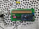
I'm currently building one and I'm testing a prototype. I can use every battery type Lto to lead acid up to 16 cel in series. It doesn't do balancing but I chose for an output to activate my active balancers wich I'm testing as well. My BMS is not cheap, I'm using expensive parts but they should outlive my battery.
Somethings I want to add in the next version:
There is rs232 to communicate with an RPI, but I will ad rs485 with rj45 connector, I'm gonna add extra inputs for current and temperature sensors, I want to add an extra voltage measurement for a precharge relais/mosfet.

First thing you need to do is, make a list of all the features you want, how many cells, how many temp/ current sensors, switches for reset on/off. Outputs for controlling relais or on board relais, indication LEDs, etc...
Then you ask yourself wich hardware you want to use, uC, LEDs, voltage regulators,... Then you start drawing the electronic schematic,....

I can tell you the hardest part is reading all cel voltages, unless you take a dedicated IC, but for 16 cells it's difficult to find.

I'm gonna follow this project. ?

I added a picture of my BMS, underneath the PCB an uC there are some other components but I first let you guess.
 

Attachments

  • IMG_20200830_082029.jpg
    IMG_20200830_082029.jpg
    127.2 KB · Views: 26
Last edited:
Most important part of the BMS is accurate cell voltage readings, as well as ability to control the output of the charge source.

The second part is where most BMS units are lacking.
 
A BMS task is:
-Cut the consumption when one or more of the cells are low on voltage.
-Cut the charging when the pack is full, by checking the total voltage or when temp is too low to charge.
-Will drain energy (turning on resistor) for individual cells if it is having higher voltage than the lowest voltage cell. (Only during charging)

Am I correct? is there more magic to it? I feel that I could be wrong, because it sounds too simple. I see diyBMS, electrodacus.. etc and think that they have worked so hard on these, so I must be missing something?

Yes. You can add balancing to the list if you want it, but some BMS don't have balancing capability as it's not their main purpose.

Then there's nice to have features like coulomb counting, temperature sensor(s), ...

The base concept is simple; however how you do it can get complicated quickly depending on what features and specs you want, and what constraints you set.

I'm currently designing my own BMS too and I'm just at the point where I finished the schematics and routing the boards of the most important and complicated parts of it. You may be interested by the design process I've gone through: https://diysolarforum.com/threads/diy-bms-design-and-reflection.4065/
 
Great to hear more BMS designs! I've also started on a BMS design a few days ago. Got the shunt current measurement operational.
 
Another thing that a BMS should do is disconnect the pack in the event any BMS component failure.
Also some designs have bleeder failures resulting in circuits shorting which is obviously not ideal.
 
I do not like all the BMSes that let the whole current go through them. I am more into electrodacus approach, that I would integrate with the source and ability to disconnect the load (inverter). The difference is that I would like to make it work with more affordable stuff like epever, not victorn stuff.
I am thinking to use one ADS1115 16-bit ADC for each 4 cells for voltage monitoring. and clamp on wire hall effect to measure outgoing current ( I know it is not that accurate, but let's see if it is that bad)

I am happy to hear about many different approaches with different focus areas.
I like the ads1115 here is a 4 channel i2c breakout. 16 channel on one bus https://cdn-learn.adafruit.com/downloads/pdf/adafruit-4-channel-adc-breakouts.pdf
 
Next thing you want to ask yourself is how you will do the electronic design around the ic, you want to read up to about 60V with an adc that can do +-6.14V. Keep in mind not every battery cel has the same ground.
 
I do not like all the BMSes that let the whole current go through them. I am more into electrodacus approach, that I would integrate with the source and ability to disconnect the load (inverter).

I don't like this approach as the BMS is a safety element that should be redundant to the other things. If the charger doesn't stop charging for example then the BMS will do its job when the cells reach the high voltage limit, but with the no FET/contactor approach it controls the charger, however that will do nothing as the charger is faulty in the first place... It's the same as having a breaker who would control the charger instead of cutting the power itself; it's not a good idea in my book.

I am thinking to use one ADS1115 16-bit ADC for each 4 cells for voltage monitoring.

As @nickskethisnikske said, unless you use an ADC for each cell (very expensive...) and isolate the digital side of them you'll have to solve the common mode voltage problem on the analog side.

and clamp on wire hall effect to measure outgoing current ( I know it is not that accurate, but let's see if it is that bad)

You can design something accurate enough for our needs, but it'll probably be more complex and more expensive than a shunt for the same final accuracy.
 
@nickskethisnikske @BiduleOhm

Thank you but I did not fully understand what you guys mean.
So what is wrong with "one ADS1115 16-bit ADC for each 4 cells for voltage monitoring" Let's say I have 4 or 8 or 16 LFP cells. As those are my focus area.
 
I will say what I did in my BMS after you found out yourself, that's really the only catch in the system. :) Because you really need to understand the limitations of the hardware electronics.

What you should do is draw a schematic of all your cells, draw them vertically on the left, then add a few adc and connect it to your uC. Put all the voltages in place referenced to your gnd. Then go looking for the datasheet. You should see you you want to try reading voltages that are to high.
 
Very nice chip, I like it ;) but I looked at the price... more than 4 USD each and there's only one amplifier per package. For 4S it's ok but for 8S or 16S it'll get very pricey and take lots of PCB real estate.
 
  • Like
Reactions: Cal
I wouldn't buy precision components on ebay personally.

Can you tell the difference between INA148-Q1 and INA148UA?

The datasheet says UA and there's no -Q1 to be seen so I don't know; usually the last characters are used for the packaging (tube, reel, tray, ...) and/or quantity, which the datasheet provides but here it's 2K5 and G4, not Q1... so I really don't know what this -Q1 is.

I'm just dealing with 4 cells.

Then that's acceptable ;)

I notice you're using OPA4990 (quad package).

Yep, around 2 USD per chip so about 50 cts per op-amp. It's basically the cheapest one I could find in the top tier brands who had the specs I wanted.
 
@nickskethisnikske @BiduleOhm

Thank you but I did not fully understand what you guys mean.
So what is wrong with "one ADS1115 16-bit ADC for each 4 cells for voltage monitoring" Let's say I have 4 or 8 or 16 LFP cells. As those are my focus area.
The problem is that it is virtually impossible to seperate the grounds from each bank of 4 so the ADC will get too many volts after the 2nd or 3rd cell
This will melt it down fairly fast. I have tried what you are trying. Without much success. But I am no EE so please keep trying you may find a solution. I just gave up and started using Chargery. Since it will pretty much do what you wish
 
Back
Top