diy solar

diy solar

Disconnect between inverters and house electrical panel

aeschbach56

New Member
Joined
Jun 19, 2024
Messages
3
Location
Tazewell Tennessee
I have 4.0 aluminum wire running from my power house to the electrical panel in the actual house. I am looking for some type of disconnect where I can hook the 4AWG wires from the inverters and then be able to connect the 4.0 aluminum to feed the house.
 
The disconnect needs to be sized to the current load. Code requires this to be calculated at 125% of the max inverter production on the label (or the sum, for paralleled inverters).
For instance: 10k inverter is rated at 10000 watts, calculation says 12,500 watts. Divide that by 240V and you have 52A and change. In this case that would require a 60A disconnect and #6 copper wire or #4 aluminum wire.
There is another limitation: the lugs need to be the correct size for the wire that is being used. You cannot trim individual strands to get the wire to fit in cases where oversized wire was used for whatever reason, voltage drop or "it's all the supply house had." They make crimp on reducers for these purposes but that will almost always be a special order item and you will need the correct tool to crimp them on, which costs around $400 depending on the size. Sometimes you can bolt on larger chair lugs to the terminals in the disconnect. Be aware that inspectors have differing views on this kind of "field modification" of listed equipment.
I have many automatic questions about the sizing of your system. 4/0 aluminum is typically used in residential applications for a 200A circuit. In this case you will need a 200A disconnect, and the wire will fit in the lugs. Is there any means of overcurrent protection on this circuit from the power house? Does the wire travel underground to your residence? It may need to be a fused disconnect not a safety switch.
I'm hoping your grid tie (if you have one) is in the powerhouse and everything already has the proper service disconnect and load protection there, and is "passing through" so to speak to get to the residence. In that case all you need is a switch, no load protection.
 
The wire travels underground from the power house to the main house. Yes it is just passing through. Proper disconnects in the power house. I want this install to be totally safe and effective even though the county I live in has no inspection on off grid applications. Did not have to pull a permit.
 
The wire travels underground from the power house to the main house. Yes it is just passing through. Proper disconnects in the power house. I want this install to be totally safe and effective even though the county I live in has no inspection on off grid applications. Did not have to pull a permit.
If it already has correct overcurrent protection (breaker or fuse) then you just need a nonfused disconnect.
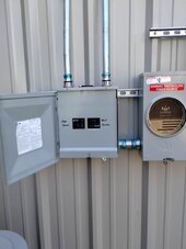
Several manufacturers make a 200A main breaker only in an outdoor rated box and this is often cheaper than a disconnect if you can get a good price on it. It serves the same purpose.
They typically have a little door that covers the breaker handle that has a locking loop so it meets that requirement.
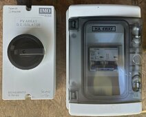
Everything going into the inverters are (will be) overcurrent protected. Coming out of the inverters with AC I don’t. Would I need to put overcurrent protection between the inverters and disconnect. If so what would that look like? By the way, thank you for your help!!!
Pics are PV and battery overcurrent protection recommended for this set up.
 

Attachments

  • IMG_3299.jpeg
    IMG_3299.jpeg
    176.5 KB · Views: 2
Everything going into the inverters are (will be) overcurrent protected. Coming out of the inverters with AC I don’t. Would I need to put overcurrent protection between the inverters and disconnect. If so what would that look like? By the way, thank you for your help!!!
Pics are PV and battery overcurrent protection recommended for this set up.
So you have load protection on the DC side but not the AC side.
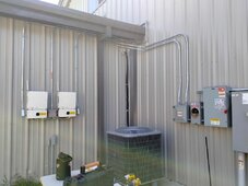
Typically if you have multiple inverters you use what is called a combiner panel to combine all of the output into one circuit. This is like a small branch subpanel being used in reverse, it isn't distributing loads it is combining sources. The output of each inverter is wired into this panel onto a breaker that is correctly sized for the inverter output, these circuits are sized at 125% of the inverter nameplate output rating. Then the power leaves this panel via main lugs or a main breaker (I advise main breaker). The circuit leaving the combiner panel is sized according to the main breaker, or if no main breaker is used, it must be sized to the total combined ampacities of the all of the input loads. Since these are sized at 125%, you can see where having a properly sized main breaker to control the output circuit might be handy.
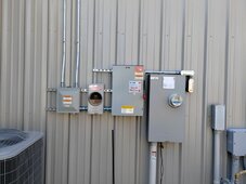
From here it would be wired to the exterior disconnect on the power house, then go underground to the structure being served.
 

Attachments

  • DuaneDuke3.jpg
    DuaneDuke3.jpg
    57.5 KB · Views: 2
  • DuaneDuke2.jpg
    DuaneDuke2.jpg
    71.1 KB · Views: 2
  • DuaneDuke1.jpg
    DuaneDuke1.jpg
    80.8 KB · Views: 2

diy solar

diy solar
Back
Top