diy solar

diy solar

Let's fight about aluminum wire!

No need for light bulbs there are some weird conditions where I can sort of see it.
But id like to see it on paper so post that if you can

Here you go. No weird conditions needed, just standard operation of an auto-transformer, including if you backfeed 240V from PV inverter into your split-phase panel, and have unbalanced 120V loads (utility transformer serves as auto-transformer in this case).

 
Gold is for kings, silver is for the peasants.
Only kings with very bad advisers; gold is not even as good as copper for conducting electricity.
So, silver for kings ...
I see you speak for the group. However my comment was not a strawman because it was to the point you made later in your post about buying supposedly copper wire (rated as such) only to find it was CCA.
I think I hit a nerve with your, "I see you speak for the group," I thought we are just play fighting in here. my apology for calling out the logical fallacy; I may have been too blunt (I've been accused of much worse before). No hard feelings ok?
 
Last edited:
Here you go. No weird conditions needed, just standard operation of an auto-transformer, including if you backfeed 240V from PV inverter into your split-phase panel, and have unbalanced 120V loads (utility transformer serves as auto-transformer in this case).

Backfeeding is a weird condition.
Or at least was, times have changed.
 
Backfeeding is a weird condition.
Or at least was, times have changed.
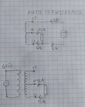
I regularly see grid L1 at -300W and grid L2 at 800W, because I set a 500W grid setpoint with the Victron ESS.
The neutral going back to the utility transformer has to deal with it.

Utility Meter still spinning forward at 500W (net). Utility Meter does not touch the neutral electrically.
Fortunately, the meter isn’t very smart.
 
Backfeeding is a weird condition.
Or at least was, times have changed.
It is for a utility transformer, but it is standard operating procedure for an auto-transformer.
We were trying to figure out how to protect auto-transformers used with 220V inverters while still allowing full wattage from inverter to reach loads.
Best answer I've got is OCP on the 220V from inverter. And thermostatic trip; otherwise you have to limit it to lower current.
Victron uses thermostat; their OCP is higher to support loads, not protect transformer.
 
After reading all these threads talking about auto transformers I think I finally understand what is being proposed, but I don't quite understand why is that a surprise. Perhaps this is due to my ignorance of the north American grid, but I thought my understanding of it was pretty close to reality.

Let's just forget the grid and consider our secondary exists on its own. So we have a "normal" auto transformer. Let's call our taps L1, N, L2 (L2 on the bottom, L1 on top).

We feed in 240V between L1 and L2. We have a load between N and L2. The N has the total load current. No more no less.

Now consider same imbalance in case of a grid driving the transformer. The load is still connected between N and L2 and the N current is still the total load current. (I reverse these on purpose. It is easier to visualise L1 as +120V and L2 as -120V as they are opposite in phase).

Then linked threads talk about things not going to plan because a poster got an X power transformer. He driven half of the windings(on one side) and discovered he can only use half of the power....hmm.

Here is my drawing.
20240607_085617.jpg
Is this wrong? An I missing something? Where is the surprise?

And if there is one, how to apply it to 3 phase transformers?
 
Yes, you've got it right.
Not really anything about the grid, except the grid is the reason we often deal with these two voltages.

The most difficult thing for people (including me) to wrap our heads around was current flow in transformer and coupling between windings.
As you've drawn for auto-transformer, current does not flow in L1 and out L2 like we expect for an isolation transformer. Current flows in L1 at the same time it flows in L2, both currents flow out N, summing for twice the current. Magnetic coupling means current through one into the load forces equal current through other winding into load.

Everyone "knows" that current in N is the difference between current in L1 and current in L2. It is like a religious belief, and they reject the preaching inspired by my Enlightenment.

If you've got an "X" VA power transformer, it can take in X/2 VA on one winding and transfer that to the other winding.
Sufficient to take "X" VA from a power source of 120V and feed "X" VA load at 240V, or vice versa.

But transformers are cost optimized and present a nasty inductive load with peak current at rated voltage. Even worse if you backfeed secondary.
My preference is to apply 120Vrms to one of the 240V primary windings, or apply 240Vrms to the two 240V primary windings connected in series (meant for 480V.) So it can transfer 1/4 its power rating, feed a load 1/2 its power rating.


Most of the issues in other threads are how to power "X" VA of 120V load from a 240V inverter, while also supporting inverter's capability of several times "X" VA worth of 240V loads.

3-phase transformers won't share power between phases at least in normal configuration.
I've tried to test a single 480V to 120V pair of windings and was having issues, not sure why with other windings open circuit, have to revisit now that I have seen the peaky currents from partial saturation.
 
I believe Aluminum wire has it's place and use for long term reliability in the proper applications such as underground triplex feeding building to building with crimp connectors just like used by the utility. As long as it is protected and moisture proof. I have buried many lines installed in 4" black plastic field tile still being used today 40 yrs ago with no issues. As far as in a home, I've repaired many manufactured homes with Al wire and most all the problems are due to connections. Never recommend any screw connections with Aluminum wire. I only use copper inside a building or home. As far as voltage drop, yes it is more critical with aluminum , say after 150' but there is ways around that as well, such as going to the next size bigger or upping your voltage if the tolerances are there in the wire size. The cost difference in a long run can all be calculated ahead of the install as copper is way out of site now days and Al has proved it's self. I am using a screw connection with triplex at my inverter but it is torqued and I can keep an eye on that connection.
 
Coming back to the subject :)

One thing to add, the kind of aluminium wire we use around here in Poland for outdoor underground connections (crimp terminated) is used direct to earth. No conduit of any kind is necessary.

However, the correct way to install it for house utility connection is to dig to locally specific depth (about 1.2 m here), put down 10cm (4in) of sand, lie down the cable, put 10cm/4in of sand on top, blue PE tape so a digger knows he's about to break through a ground cable. And only then fill the rest of the trench.

Also there is alway an excess loop of cable buried just in case before the connection box.

Edit: I forgot to say, we used ribbed blue pipe (sort of conduit) where the cable was going to the surface and into a box. To protect it from UV, rodents and freeze/thaw cycled. That pipe would go 1m above ground and be closed off with polyurethane foam. It would also go down to the full depth, but then horizontally it was just the cable.

Back in the day when as a kid I was helping my dad (an electrician) by making such installs, we would always leave a small section of the trench open for the inspection. And only after it would get filled.

I suppose in other places people use conduit instead?

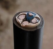
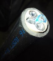
Here are few pictures how a "modern" Polish made aluminium ground cable looks like. This is the thinnest you can get. 10mm2 or awg7.


20240608_083553.jpg20240608_083650.jpg
This grey stuff between the main insulation and strand insulation is some sort of cushion (a bit rubber like but it crumples in hand). Bigger cables sometimes have a load bearing line in the middle.
 
Last edited:
Pretty normal looking
I never seen Polish cable before

Dobry!

Assuming your doing something that looks like normal continental wiring you are going to feed that from 16 amp protection device

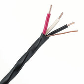
Our cable has m Canada for a residential application is called NMWU
NON METALIC
WET location
UNDERGROUND
1717895378219.jpeg
Pretty typical of most places gravel in a trench
Add some sand to cover cable
Some safety tape to warn a digger they are going to dig up a cable
These are just good practice and common sense rules.

We burry between 60cm and 90cm
We make an S with wire at the ends of the run to on allow for frost to move where a cable comes up to a building.

Same idea

It’s nice to see how others do it

Typically I notice countries in the EU have rules and standards a little more stringent than here
I assume it’s about higher operating voltages
I’m not fond of electrical equipment made to IEC standards since they do not mesh well with our codes and ways of wiring things.

Did GOST ( гост )influence electrical and construction equipment and practices in Poland at one time?
In Canada and Mexico the influence of American standards by NFPA ( fire protection ) directly influences the way we build and wiring things.
 
Last edited:
Pretty normal looking
I never seen Polish cable before

Dobry!
:)
Assuming your doing something that looks like normal continental wiring you are going to feed that from 16 amp protection device
Actually I will, because I'm only using strings of ~11A panels, but this particular cable is acceptable for quite a bit more. Constant long term current (3 conductors with current, one without, single cable in soil temp 20C, air temp 30C, allowable cable temp 90C) in soil is 68A (sounds pretty high right?) . How come?

This is YAKXS 0.6/1kV
Y - outer sheath is made of PVC
A - Aluminium
K - type of cable - power cable (sorry I'm not sure how to translate this, it also has a meaning of utility power supply etc)
XS - cross linked polyethylene insulation.

0.6/1kV - good for 600V AC or 1kV DC.

It is using cross-linked polyethylene making it fine for constant temperatures of 90C, 130C "temporarily" and 250C "during a short" (this is very brief, it is expected a breaker will activate).

We have various official example tables of currents acceptable for wires and they are usually quite conservative. For example ground temperatures at depth are about 10C so taking 20C means it has been heated quite a bit.

The manufacturer provided constant current, 3 conductors equally loaded in soil is 65A for this cable.

Most electricians would probably be fine with 50A breaker for this cable on its own very conservatively.

However I have 3 touching so I have to derate by 0.75. Also I might be using all 4 wires with current in some of these cables in future. Another 0.8derating. So in my case 40A is the most I should ever run it at.
Did GOST ( гост )influence electrical and construction equipment and practices in Poland at one time?
In Canada and Mexico the influence of American standards by NFPA ( fire protection ) directly influences the way we build and wiring things.
I think our cable naming standards are a translation of GOST, but interestingly for technical standards German standards have influenced Poland a lot more.

There was East Germany back when GOST would affect us, and (probably wisely) it was decided to mirror german standards a lot. In fact if there is a long lived German standard. It is very likely there is also a very similar Polish standard. Many manufacturers of items (for example hydraulic fittings) stamp both on their products.

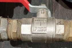
For example this fitting
20240609_110633.jpg

You have DN25 for Germany, 1 - for 1 inch and PN25 for Poland.
 
  • Like
Reactions: DPC
Hmm....
I Never knew what the DN meant I have seen that on valves before.
Now I will look for PN to see if they are of Polish manufacture.
 

diy solar

diy solar
Back
Top