diy solar

diy solar

DIY 'Chargenectifier'

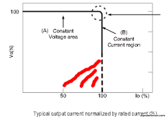
You definitively don't want constant current all the way to max voltage IMHO when charging the battery. We'll not when you don't know when the maximum voltage is at least.
Yeah I'd get the voltage adjustable model for that reason.

I want to get one of the 600w above to test. I like that the charger has a higher overvoltage rating but it's fixed config 3 stage and I'd honestly rather have the on off behavior of the driver for my application of trying to backstop the bank, rather than fully charge it.
That's just a little over 10A though... Are you sure that 600W will be enough for anything useful apart from testing? Don't know which battery you have, if 100Ah or 280/304Ah, but it's going to take a while. When I started testing my battery all I had was a 250W adjustable power supply... It took AGES to charge up the battery even so slighly. Thankfully then I used the inverter and got something out of the last day of sunshine ?.

Whether it's from a generator or grid rating seems a bit small. And I'm not fond of running power supplies at 100% load.
 
I'd like to get to maybe 3kw of DC supply eventually but avoid spending $1000 on a product that turns out not to work for me at all.

I'm ok with running them 100% and I'm ok with a creating hodgepodge supply of a 180w+600w LED driver + 2300w charger or whatever, as long as they don't disagree with it. I like the LED drivers predictable behavior, you set the point voltage and they will CV or CC their way to that. No stages.

CV when the battery is falling into the driver's voltage, and CC when it's coming up from below, if I understand it correctly.

1699296084560.png
 
So this thread is super interesting, so interesting that I got me a whole flatpack2 power system to throw in a server rack, with 6 of the 3000W models.

It came with a smartpack controller that seems like it can be controlled via snmp or CAN so I was going to see if libreNMS or some other management software will allow me control over the voltage and current of all the units simultaneously. If not, I will have to come back here and bug you guys for some programming help :D now I just need to find a generator that can run them all at the same time, I only have 5-6k to play with on the little briggs I have.


Nice! I saw those and an ESP32 project, but I haven't received them yet to start messing about. My goal is to have a decent UI and web page that I can monitor/ change settings if needed, and setup some automations with home assistant if I manage to get that far.
 
Do you know if they will have half the output at 120V? That's a great price.
Here is the cut sheet https://www.power-solutions.com/wp-content/uploads/2012/02/EV-Flatpack2482000HERectifier.pdf

While it is clear they will operate down to 120V AC (or DC) it is not clear what the output would be. I would expect it could be a little more than half?? it could be as much as [11.6amp (peak input rating)]*[120v]*[90% full load efficiency]*[0.99 power factor] = 1240 watts? It is probably input current limited, I couldn't find any details on the internet. Personally I intend to run from a 240v generator.
Thank you. I have a big 240V I could use, having the option for the small 120v inverter would be nice as well.
I might finally have to build one.
 
Has anybody found any of the custom circuit boards for the flatpack2 in the US? There are several on ebay plus this one online but all in Ukraine or Lithuania. I will if I must but rather not wait for it to get shipped half way around the world.
 
Great info on setting voltages in here. I only read the first 2 pages and it was figured out.
 
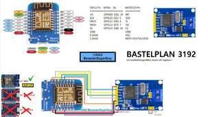
I've finally been able to play with my Emerson R48, a WeMos D1 Mini and an MCP2515 CAN controller.

This controller (get it on AliExpress): -

1703928898027.png

Wired like this: -

maxresdefault (1).jpg

With the 5V/3.3V Vcc mod (cut one track and add a wire). https://forums.raspberrypi.com/viewtopic.php?t=141052

Using this library https://github.com/coryjfowler/MCP_CAN_lib/tree/master

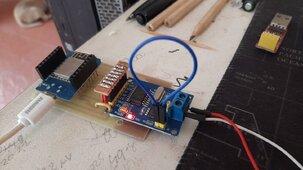
Prototype, I gave up with breadboards long ago (flaky connections, and when it works you still have to make a board), with a baby NC mill/engraver I can make a board in a couple of hours and no nasty chemicals: -

200772.jpg

Very, very early days, but I can set the output voltage via the USB :)

The idea eventually is to be able to demand a charge power to negate any energy export.

Anyone else going in this direction?
 
For anybody working a similar use case here are some quick instructions on how to permanently change the supply voltage on the Eltek FLATPACK2 units mentioned by the OP and in #307 above. I received the three units I ordered - well packed as described. They were all set to the default voltage of about 53.2 though.

Right now I only intend to use them for periodic charge from generator so I really just wanted them set for full 2000watt output but with a voltage I can fully bulk charge from - I picked 56.3v. At some point I'll get fancier but the quick version:

  1. I bought one of these as an isolated USB to CAN interface (https://www.amazon.com/dp/B0CDGGBZDT?psc=1&ref=ppx_yo2ov_dt_b_product_details)
  2. Downloaded cangaroo from here
  3. I bought these interface boards for permanent installation. But because I was in a hurry to play I just connected the CAN terminals on the FLATPACK to the CAN interface using probes
  4. This thread @42OhmsPA and others noted gets all of the credit for hacking the protocol. I'm just abbreviating their key findings here.
  5. Connect CAN-H to CAN-H and CAN-L to CAN-L - for a short temporary wire run twisting, shielding and grounding aren't really needed.
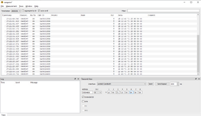
  6. Power up the flatpack and "Start Measurement" in cangaroo - it will ask you to confirm bit rate - set to 125000
  7. Right away you should see messages like the below with the unit sending out its serial number - neglecting the "1B" that may be in the first byte for the first few messages the SRN should match the sticker on the case.
  8. Following post #42 I issued address 05 00 48 08 and a message containing 8 bytes (DLC=8). 6 bytes of the serial number and 00 00 for the remaining two bytes to login to the unit and set its ID to "2" - screen shot below
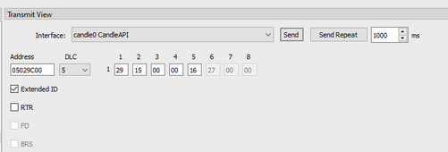
  9. Then from message #58 in that thread if you issue address 05 02 9C 00 followed by a 5 byte (DLC=5) message 29 15 00 LL MM where "LL MM" is the desired voltage from post #50. you should get back a message starting with 2B but containing your "15 00 LL MM" as confirmation. Note that in the #58 post I'm quoting they set the address to 01 but in this example it has been set to 02 - hence the bold.
  10. After step 9 the voltage won't change right away (that is a different command - see that thread) but it will change after you power cycle it and every time thereafter.
  11. Now I should join the endless-sphere.com forum just to thank those guys even though I don't have an e-bike :)
initially reading the CAN messages with device serial number. The "Transmit" message is for login in my case serial number is the 12 43 71 15 95 89
1704245377293.png

issue command to change voltage on the unit
1704245444051.png

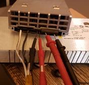
hackish job of probing the unit. Don't try this at home :) and don't short the terminals. But if you do try this at home 12AWG solid is a good diameter to hold in the power connections.
1704245521728.png
 
Last edited:
The CAN interface board does actually work on 3.3V, but the driver device isn't specified to 3.3V so add the mod if you like.

And I found and easy-peasy way to convert float to hex to send to the Emerson from Arduino / ESP8266 etc.

It doesn't look like the forum supports "code" tags :(

==========================
void FloatToHex(float f, byte* hex){
byte* f_byte = reinterpret_cast<byte*>(&f);
memcpy(hex, f_byte, 4);
}

void setup() {
float f = 3.10;
byte hex[4] = {0};

FloatToHex(f, hex);
//... do stuff with hex now...
}

void loop() {

}
==========================
 
If you want to do this without the memcpy() and in plain C:

C:
union converter{
  float float_val;
  unsigned char hex_val[4];
};

int main(){
  union converter c;
  c.float_val = 123.456f;
 
  /* Your hex result: c.hex_val[] */
  printf("%x ", c.hex_val[3]);
  printf("%x ", c.hex_val[2]);
  printf("%x ", c.hex_val[1]);
  printf("%x \n", c.hex_val[0]);

return 0;
}


It doesn't look like the forum supports "code" tags

It does. Click on the three vertical dots in the editor next to the 'text color' option and the 'insert table' option. Both code and inline code are there.
 
Excellent ^^^

Meanwhile, gleaning info from endless-sphere and some testing: -

To read from the R48

Send to 06000783 => 01 F0 00 xx 00 00 00 00 where xx = measurement No.
Response from 060F8003 <= 41 F0 00 xx yy yy yy yy where xx = measurement No. yy yy yy yy = value
EDIT - Fixed the response address

xx =
01 = output voltage
02 = output current
03 = output current limit
04 = temperature in C
05 = supply voltage
06 =
07 =
08 =
09 =

This saves me the hassle of building hardware to monitor the output of the beast!

@upnorthandpersonal convert those 4 bytes to float??
 
Last edited:
Back
Top