diy solar

diy solar

DIY solar hot water controller options?

callmeburton

New Member
Joined
Mar 4, 2022
Messages
258
Has anyone DIY'ed their pump controller and if so what did you use?

Inputs I want to monitor, log, and use to turn on / of pumps and or valves.
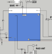
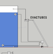
1) temperature at the top/bottom of the solar water tank, and at the output of the collectors.
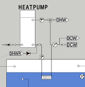
2) temperature of water coming into an isolated DHW tank (aka ground water temp) and the temp in that tank as well.
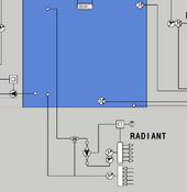
3) flow sensor of water going to collectors, DHW use, hydronic radiant heating use, and possibly boiler use
4) temperature of water going to/from boiler
5) temp sensor of water going to/from hydronic radiant heating

General logic I want to code in.
(This is for a drain back system)
1) When top of tank is at 160F turn off the pump, do not turn on pump again till tank is 145F assuming the collectors are still hot enough to supply hot water to the system (this is the deadband).
2) When bottom of tank (supply to collectors) is at X degrees and the collectors are at X+Y degrees and the top of the tank is < Y degrees turn on the pump.
3) When tank temp is below 90F "call for a boiler" (the hydronic system will be directly plumbed to the thermal mass tank) ... we won't have an automated boiler so we will have to manually load / feed the boiler but an alert light would let us know without having to check apps / screens / etc. The boiler will have an exchange coil in the solar hot water tank .... less I can be convinced to directly pipe it to the tank as well.

General logic for the DHW side of the equation.
1) When ground water coming in is below tank temperature allow flow from ground water through tank coil to the DHW tank (this will likely always be allowed so it might not be needed and just plumbed up straight through the thermal mass tank)

General things I want to track in a database and visualize.
1) Hot water use in the system (flow, amount, BTU, temps in / out)
2) When the solar pump is turned on / off, flow, btu, temps in / out
3) When the boiler is used, its flow, btu, temps in / out etc.
4) overall tank top / bottom temp sensors over time
5) hydronic input / output temps / flow / btus

So for equipment I think I am looking at
1) 2 - 3 flow sensors
2) 2 - 3 pumps
3) 9 temperature sensors
4) some type of DIY controller, currently have an older phidget 8/8/8 I was thinking of using / programming / etc.
5) screen interface or web landing page for tracking / graphing etc.
 
Going to use my original post here on the topic to branch into what I think is my main design less super fancy all in one automation.

Feedback welcome!

waterSystemDiagram (6).png

Basic components.
Boiler
, has a circuit dedicated to "saving" the boiler if the water gets too hot by dumping water into the drain if required (pictured left), and the main boiler (right) which prefers to operate at 140F or greater before running water through it. A basic thermistor controlled pump and a valve serve the purposes above.

Solar Evac tubes, drainback system.
I did find a controller which I think will do what I want it to and do some logging. It can take in 4 temperature sensors and control the relay based on these 4, it can also control up to 2 relays. 5 arrays of 30 tubes, will be roof mounted, pump head about 25ft required. Temp sensors at bottom of tank, return line, and top of tank.

DHW
I think I am going to use a heatpump tank to "make up the difference" if required. DCW will come in through the large thermal mass tank before entering tank. There is also an instant hot water return pump on the hot water side I will be implementing.

Radiant heating
I don't show all the zones in this as it is done for a basic overview level. The radiant will have its own controller(s) and zone control using standard thermostats of some sort. Pulling directly from the large thermal mass tank will allow for the most efficient use of the mass.

The elephant in the room, the tank.
I am going to DIY a tank based off some other designs I have seen commercially ... I think I can get about 900 gallons and still have a good head room at the top for the returns where required. ~4.75" of polyiso will be used to insulate the tank and I am going to install two liners and an insulated top. All plumbing will come in through the top of the tank and it will not be pressurized ... not pictured but I need to add a immersion vent to allow for steaming out of the collectors on rare occasions.
 

Attachments

  • waterSystemDiagram (5).png
    waterSystemDiagram (5).png
    23.4 KB · Views: 10
  • waterSystemDiagram (4).png
    waterSystemDiagram (4).png
    19.6 KB · Views: 8
  • waterSystemDiagram (3).png
    waterSystemDiagram (3).png
    16.5 KB · Views: 7
  • waterSystemDiagram (2).png
    waterSystemDiagram (2).png
    21.7 KB · Views: 7
  • waterSystemDiagram (1).png
    waterSystemDiagram (1).png
    21.1 KB · Views: 9
I don't have much to add, but this is interesting.
I'd probably just run an Arduino and relay that, but then you've got to write all the code yourself, easy to miss an edge case and brick something. Similar story for an off the shelf PLC.
 
I am fairly confident in my ability to code this up if I could find the right platform to do it on. My "real work" when I am not building the house involves complex coding so I am good there :D

For now I need to get this system up so I can see where the radiant is in the floor so we know where we can attach framing and where we can not (since the floor plan changed a little post pouring the slab) so I will likely wire up the solar evac tubes and the boiler as pictured after I build the tank. I might even setup the solar inside and have it running to a smaller temp tank just to get it going as well.
 
One of the things I am finding difficult right now is parting everything out ... so I am going to start listing things I am going to use for the above "just get it done without sensors" build for future viewers.

I will likely edit this single posting to add parts as I get them / find them

Used by all, potentially
  • 24V 40VA Control Transformer 40VA, Primary 120, 208, 240V Secondary 24V, HVAC Furnace Multi Tap with Foot Mount (will terminate likely at a distribution din rail or something fused)

Boiler loop Main
  • RANCO ETC-111000 Digital Cold Temperature Control (delta T controller, will send signal to pump relay)
  • Inkbird SSR Solid State Relay SSR 40DA for PID Thermostat Temperature Controller (pump relay, different pumps take different "signals", taco I think take 24vac for example but this can be universal for any signal required)
Boiler secondary "emergency" loop
  • RANCO ETC-111000 Digital Cold Temperature Control
  • Inkbird SSR Solid State Relay SSR 40DA for PID Thermostat Temperature Controller
  • Pressure Reducing Valve, DN15 1/2 inch Brass Water Pressure Reducing Valve Water Control Pressure Regulator Valve (I think this needs to be 3psi for our stove)
  • U.S. Solid 1/2" Brass Electric Solenoid Valve 24VAC VITON Seal N.C. (Air, Gas, Fuel.) (notice the 24vac signal again)
  • 1/2" brass check valve

Hydronic loop
  • pump tbd, trying to figure it out as I have 3 manifolds ... 1 with 2 zones, 1 with 4 zones, and 1 with 5 zones.

Evac drain back loop
  • ThermokLogger-4A (this is the logger / controller and should provide the logic requested above in the original DIY thoughts)
  • Thermistor, NTC, 10k, #4 ring terminal, 154 mm (6 in) long (sensors for the controller above)
  • AC adapter, North American, 9 VDC, 5 watts (to power the controller)
  • 0013 Variable Speed Delta-T Cast Iron Circulator Pump, 1/6 HP (might seem overkill but I have at least 25ft to overcome at startup. Also this is cheaper than a 0011 variable pump which might just do the job) This comes with 2 sensors and will adjust flow as required to get as much out of the solar as possible.

Heatpump loop
  • readytemp hot water circulation loop (notice the DHWR, this is what is pumping that return)
  • Flexible stainless steel coil (a lot cheaper than copper with similar properties for heat transfer) based on my use case of 6gpm in winter with 40 degree water and 110 output to faucets and a 160 storage tank I would need ~240lft of 3/4 or ~170lft of 1" ... depending on head loss these would be multiple coils provided for 3/4" pipe copper at 100ft it would be ~6ft at 6gpm and ~2ft for 1" pipe ...
 
Last edited:
Nice system! I'm pondering something similar at my new house build - you may be inspiring me. I started in solar thermal (vs PV) and still passionate about it but I am questioning whether I could more flexibly do the same thing with just PV - yes it will take more panels due to less efficiency.

Are you running glycol in the big tank? I did some big solar thermal projects with this awesome guy (Ken May) and he would just jam copper tubing in the big tank for a heat exchanger to your DHW heat pump.

For controls, if it were me, you have enough going on that I would do one PLC vs the various loggers and temp controllers. Makes it easier to log, change settings and sequences, even remote into if you need to.
 
Last edited:
Are you running glycol in the big tank?
shouldn't need to with a properly setup drain back system. You always shut the pump off when the bottom tank temp is only 5 degrees bellow the collector tank and when the top of tank temp is 160F. So the collectors and insulated pipe is typically above tank temp and has time for water to leave the system (this assuming you setup your 1" drop in 20ft correctly for the manifolds / pipes)

just jam copper tubing in the big tank for a heat exchanger to your DHW heat pump
The amount of copper I would need for that is like 1-2k for the load I am trying to account for :/ ... so likely going to use flexible stainless steel in its place as I can get it a lot cheaper than copper and from what I have seen it will "work" as expected.

For controls, if it were me, you have enough going on that I would do one PLC vs the various loggers and temp controllers.
I don't disagree with this approach but I also want the data / sensors to control everything as well as log. I am need to get parts of this system up fast so I can see the radiant piping in the slab which will enable me to start framing up the walls as our floor plan changed since we put in the radiant loops. Long term I will likely have an array of flow / temperature / pressure sensors on a logger which I can use to visualize the data and actuate relays to turn off / on different pumps. The ThermokLogger-4A above kind of does this but only with 2 relays and 4 sensors. I want to track more than just this overall and have it in one place to track performance of the solar passive house I am building given the amount of "unconventional" stuff I have integrated into the design and construction.
 
Back
Top