MaikaiLifeDIY
Solar Enthusiast
I would update your picture "the whole picture" and post it back again for one last review.


Amen!!! ThxI would update your picture "the whole picture" and post it back again for one last review.
The only thing I see is that your Shunt doesn't seem to be reporting to your Cerbo, which maybe you will use Bluetooth. Otherwise, it all looks good from my perspective.Amen!!! Thx
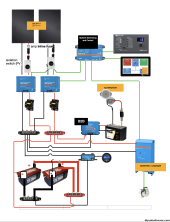
not sure if you were looking at the updated file I posted two replies up…. Replying to Maikail.A few things I noticed- you have a “Digital Multi Control panel” next to your Touch display. You don’t need it - everything it does can be done in the Cerbo. It is for if you do not have a GX device(Cerbo).
Bus Bars. Take a look at the Victron PowerIn. If it will fit. There is a YouTube video showing how to attach fuses. They are really good high quality bus bars and often don’t cost much more than a set of other high quality bus bars. Don’t use cheap bus bars! They must be copper not brass. And they need covers.
Wire Size. You do not indicate the wire size of each set of wire. I like seeing that on the plans. Another thing to double check - helps to prevent installation a wire that is too small.
Fuses. I don’t see fuses on your diagram. (Including the size needed). They are very needed in Marine settings.
12v loads. I don’t see a wire going to your 12v fuse box for 12v loads. One thing I did on my MotorHome is I installed Victron Smart BP65 (battery protects). This was so if I left loads (lights) on, it would shut off the 12v fuse box when the battery was low, but before it was dead. It makes it so the BMS does not go into shutdown and you don’t have to figure out how to wake it up. The next day the solar just charges the battery.
Also, does your battery have Bluetooth- so you can see if the cells are getting out of balance? Hopefully-Yes.
Good Luck with your project.
So if I add Bluetooth device I do NOT need to connect SHunt to CErbo?The only thing I see is that your Shunt doesn't seem to be reporting to your Cerbo, which maybe you will use Bluetooth. Otherwise, it all looks good from my perspective.
I have 2 Dakota Lithium Life04 batteriesYou do need to connect your Smartshunt to your Cerbo via a VE.Directcable or a ve.direct to usb adapter and then a usb extension cable. What connecting the Smartshunt to the Cerbo does is it sends the battery voltage, current, and state of charge to the Cerbo. In the Cerbo you will enable DVCC - all that data (plus the battery temperature- which cable is included with the Multiplus) will then get displayed on the Cerbo and the data will get passed to each device.
The DVCC helps each device compensate for wiring losses and can prevent low temperature charging. For example, in my MotorHome, my 2 SCC’s are a ways from my battery (no where else to put them) and inside where my battery is basically outside. Because of the distance I have voltage drop on each one - one I ran thicker shorter wires and I have less voltage drop - one I reused OEM wires and it has a much longer run and more voltage drop. But because they know what the voltage is at the battery (from my BMV712), they can pump out a higher voltage so when it hits the battery it is the 14.2v I have programmed.
The BMS (Battery Monitoring System) is inside the battery and included with it. Watches over the cells - if they go too low - it shuts the battery down (under voltage), if they go too high it shuts the battery off. It also balances the cells (or tries to) in the top of the charging cycle. I like to have the bms report it data on an app (everone uses Bluetooth), that way you can check for yourself that the cells are well balanced- and if not take corrective action to fix the issue you caused (not charging to a high enough voltage at a slow enough rate to give the bms time to re-balance the cells). While some manufacturers do not consider it a necessary addition, I want some way of looking at that data. YMMV.
Also, on the battery BMS’s. The battery you select will have two ratings that can easily be confused.
Ah - amp hour - this is how many amp-hours the battery capacity is. The bigger the number the longer it will power a device until the battery is empty.
A- Amps. This is how many amps the bms can deliver at once. (Usually 100a or 150a). When your run a high load on your Inverter the inverter will need a LOT of amps to power it. Batteries in parallel- you add the amps.
What is the biggest load you plan to run on the inverter? Your picture has a smaller inverter.
I made my own battery (DIY). Unfortunately I do not know which batteries are good ones that will meet all your specifications.
I actually did a summary of what I'll be neededAlso, if you haven’t already done this you need to figure out exactly what you plan on powering and how much power it uses and how long in a day you will be using it. This way you set your power budget correctly.
This way you set the constraints on your system correctly. For example, if you want to use a microwave for 15 min a day you system needs to be big enough to run the Microwave (Amps) and have enough energy stored to run it that long (Ah) and enough solar panels to refill the batteries when the power is used.
(I used a microwave as an example- I think your inverter you selected is too small to run a microwave).
In the Cerbo you will enable DVCC - all that data ... will then get displayed on the Cerbo and the data will get passed to each device.
So if I add Bluetooth device I do NOT need to connect SHunt to CErbo?
You do need to connect your Smartshunt to your Cerbo via a VE.Directcable or a ve.direct to usb adapter and then a usb extension cable. What connecting the Smartshunt to the Cerbo does is it sends the battery voltage, current, and state of charge to the Cerbo. In the Cerbo you will enable DVCC - all that data (plus the battery temperature- which cable is included with the Multiplus) will then get displayed on the Cerbo and the data will get passed to each device.
I'm curious, xavpil has what looks like non-smart batteries, so the Shunt tells the Cerbo if the battery is charging, charged, discharged, dead etc. Why would you want to enable DVCC and override the internal MPPT charge algorithm?Yes I would because it will pass the info to the SCC mppt’s.
Is there a shutoff switch between the busbars and the inverter DC input?Amen!!! Thx
No. Should there be?Is there a shutoff switch between the busbars and the inverter DC input?
I'm curious, xavpil has what looks like non-smart batteries, so the Shunt tells the Cerbo if the battery is charging, charged, discharged, dead etc. Why would you want to enable DVCC and override the internal MPPT charge algorithm?
That makes sense, except when you say "my inverter can pump out 120a", your inverter would take 120a from the battery, not push into it. Or is your inverter like an inverter/charger?There is a lot it can do- in my case my inverter can pump out 120a, one mppt can do 50a, another can do 30a - that’s 200a - way too much for my battery- so I can set a 100a charging limit and combined all three devices will not exceed 100a.
Also, because of OEM wiring- one of the mppt’s has really long wire run and will have voltage drop. The DVCC adjusts the voltage so the voltage at the battery is what is programmed into the mppt.
Also, it sends out the battery temperature- and if the temp is below 40F (I set that) the mppt does not charge.
Three uses on my system - there are a few more.
Yes I have a Multiplus inverter/charger and I was typing about the charger aspect.That makes sense, except when you say "my inverter can pump out 120a", your inverter would take 120a from the battery, not push into it. Or is your inverter like an inverter/charger?
I was looking at my Victron system and my DVCC is enabled, but I only have one MPPT and no other source of charging so possibly not as useful in my situation, but.. that is good information and I hadn't dabbled with that setting much.