diy solar

diy solar

Doing something wrong? Testing low power inverters with Oscilloscope

Destination: Moon

New Member
Joined
Apr 26, 2022
Messages
17
Location
Planet Earth
Hi,

Was interested in seeing how good or bad inverters are. I'm new to solar and oscilloscopes..... Although I've always wanted one. Even though I don't know what to use it for.....

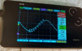
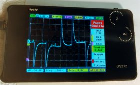
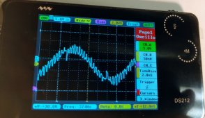
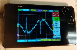
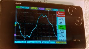
Attached are a few pics of my test results. All plots were auto ranged with me stabilizing the display. Some don't look right but I couldn't get them to look like I thought they should. Welcome any help or comments - thanks
 

Attachments

  • Bestek 500.jpg
    Bestek 500.jpg
    224 KB · Views: 11
  • Power Wave 300.jpg
    Power Wave 300.jpg
    239.4 KB · Views: 11
  • Giandel 600.jpg
    Giandel 600.jpg
    232.1 KB · Views: 11
  • Kodiak.jpg
    Kodiak.jpg
    204 KB · Views: 12
  • Household 120v.jpg
    Household 120v.jpg
    253.2 KB · Views: 12
Although I am not surprised at some of the inverter outputs, I am very surprised at what your 120V looks like. That must be a pretty cheap scope or you were not using a ground.

With 120VAC, you should be getting around 340V peak to peak. I am guessing you are using a 10X probe.
 
Last edited:
None of them look right.
Did you take them under load? How big?

This is what the wave looks like on a 40-year-old Philips scope.
CCC (Cheap Chinese Clone - MUST pv1800 vmpk). Almost no load (<100W).

oscil.png
 
Although I am not surprised at some of the inverter outputs, I am very surprised at what your 120V looks like. That must be a pretty cheap scope or you were not using a ground.
I was using the ground. But your right, it's a tiny battery powered scope that I thought would be ok for hobby use but maybe not... Or I got a bad one. The plot of the household does look bad. Could the fact that it was from a coiled 50 foot extension cord be creating distortion?
 
None of them look right.
Did you take them under load? How big?

This is what the wave looks like on a 40-year-old Philips scope.
CCC (Cheap Chinese Clone - MUST pv1800 vmpk). Almost no load (<100W).

View attachment 93355


Yes, I was powering 2 incandescent light bulbs with the inverters at the time. Figured that would show the power quality?

But thinking some more, the scope has a signal generator and the sine wave looked really good, at 1khz and low voltage
 
Last edited:
I was using the ground. But your right, it's a tiny battery powered scope that I thought would be ok for hobby use but maybe not... Or I got a bad one. The plot of the household does look bad. Could the fact that it was from a coiled 50 foot extension cord be creating distortion?
That won't matter.
 
I bought one of these a couple years ago on Amazon for $330 for hobby use...Arduino and stuff like that.


More money now but it is a great scope for the money. I am a retired EE and am used to using scopes costing many times this and it holds it's own for home stuff. Originally I was going to buy a used Tektronix scope but this is WAY better.
 
5W each? 500W each?
What do they look like with no load?
-

The household was no load but from a coiled extension cord. The inverters were powering 135 watts. I disconnected one bulb and didn't see a change while I was testing. I'm probably gonna buy a better desktop scope. I'm fascinated by these things and they aren't crazy expensive nowadays
 
I've seen line AC look that bad though generally around industrial areas. The spikes at the peaks are where the H bridge flips, an extra long delay.
 

diy solar

diy solar
Back
Top