diy solar

diy solar

EG4 18k Proper Wiring and Software settings for whole home backup, help!

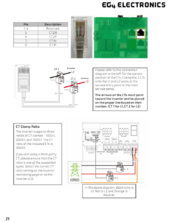
CTs rated for 1/1000, 1/2000, or 1/3000 should be functional. The CTs can be wired for an Ethernet connection using the pinout provided in the manual. Although this setup is not recommended, it is possible to wire the CTs supplied with the inverter inside the inverter box, which may result in interference on the CT. Also, I would review the previous post. It looks like some extra pictures were added by accident.
1718722637641.png1718722504013.png
 
CTs rated for 1/1000, 1/2000, or 1/3000 should be functional. The CTs can be wired for an Ethernet connection using the pinout provided in the manual. Although this setup is not recommended, it is possible to wire the CTs supplied with the inverter inside the inverter box, which may result in interference on the CT. Also, I would review the previous post. It looks like some extra pictures were added by accident.

View attachment 222886View attachment 222885
Thanks @EG4_Jared . So based on this diagram, it looks like the CT go on the conductor wiring from L1 and L2 from the inverter, preferably in the panel (which this diagram makes it confusing)?

If that is the case, how does the EG4 monitoring system know what the actual consumption is from the panel/grid? Because wouldn’t this just be monitoring what is being produced by the PV system and then what is being pushed to the panel/grid?

One other question is besides the CT sample ratio, is there any other software set up that needs to occur for the CT to work properly?
 
Got it thank you. Do you have recommendations of other CTs that may work?
I’d ping EG4 to see if they can recommend a ribbon CT and/or energy meter combo. It should exist. Sometimes ribbon CTs come with an active analog to analog signal massager to make it work more like other CTs

One of those conductors from the meter side is making a super tight curve.

Searching Google just finds my own posts asking about whether EG4 has ribbon CTs
 
Last edited:
So based on this diagram, it looks like the CT go on the conductor wiring from L1 and L2 from the inverter, preferably in the panel (which this diagram makes it confusing)?
That looks like a simplified cartoon that (for better or worse, probably worse) omits the main panel busbar.

Is it clearer in the big ass wiring diagram with fuller details?
 
Another approach is to have an electrician pull the meter and attempt to pigtail an extension onto those conductors going into the top of the main breaker

Pulling meter requires coordination with PG&E. They get very upset if you cowboy it. And you will have to pass AHJ inspection on the pigtail before they allow you to turn on.
 
I’d ping EG4 to see if they can recommend a ribbon CT and/or energy meter combo. It should exist. Sometimes ribbon CTs come with an active analog to analog signal massager to make it work more like other CTs

One of those conductors from the meter side is making a super tight curve.

Searching Google just finds my own posts asking about whether EG4 has ribbon CTs
@EG4_Jared what are your thoughts on the above? Have you had other customers with this issue (EG4 Cats are too bulky and won’t fit in panel)? Assuming you have do you have recommendations for other CTs that will work?
 

diy solar

diy solar
Back
Top