Kaiser57
New Member
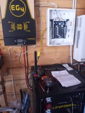
Good day folks! Newbie here, 1st decent sized system for me. Just installed my EG4 6000ex 120/240 inverter with 3 EG4 48V LiFePo batteries in a server rack. I have it connected to my main panel which is grounded to an 8' long ½" copper pipe driven over 7' into the ground. The main panel has zero loads on it except for a single dewalt 20V battery charger as my test that it's all working. I have full 120/240 in my panel.
Every time I fire up the inverter within a few minutes the red LED on bottom right of LCD screen starts flashing and it beeps once a second and will not stop. It appears to be going into warning mode but no warning codes pop up or anything else. It does this with or without the panel connected.
There is no PV panels connected yet and only a honda inverter generator used to charge batteries as this is totally off grid, panels will be setup and connected once winters done. No steady AC or PV input at all. It seems no matter what I do or try the warning always comes on and it keeps producing AC power for 7 minutes or so even in warning mode and then the inverter eventually stops producing AC current.
Everything is hooked up properly, no wires crossed etc...even with everything totally disconnected(meaning all wiring physically disconnected) except for my batteries hooked up it still goes into warning mode with no codes. All battery communication dial switches are set the same, 1 is on 2, 3 and 4 off. I've read the manual numerous times thinking perhaps the battery server rack needs to be grounded but can't find anything stating that nor does it seem that the inverter itself can be grounded until its connected to the main grounded panel. All wiring installed was done with the wiring sized and supplied by Signature solar.
I'm well versed in regular residential wiring but can not for the life of me figure out what the problem is here. Anyone able to show what I'm doing wrong or missing lol? Thanks in advance for any help!