diy solar

diy solar

Eg4 6000EX help

Quankl

New Member
Joined
Apr 10, 2022
Messages
140
I've been through the wringer with this...

I have my inverter...

I swear everything is correct.

Positive to Positive. Battery cables
Neg to Neg. Battery cables.
Nader DC breaker from Signature recommended for the setup.
Inverter is output to a breaker panel. Separated N and G. Hot1 and Hot2 into a breaker 40A with 10awg as per the manual to feed the breaker.
One circuit in this breaker panel that is going to be running. (Kitchen fridge small. 150w idle. 700w defrost.)
I have AC input from a bonded main panel. Two Hots from each leg, a N and a G.
Setting 34 set to Enable
I open close the main Battery DC breaker.
I open close the actual breaker on the physical battery to let current flow to the inverter.
I press the power button on the Inverter panel.
Inverter sends 119.8v to the receptacle verified with voltmeter. Which is expected.
I then go to plug in the fridge. Inverter shuts down BP.
I am dumbfounded. I plug in a standing fan like 60watts. It runs for a hour and 20 minutes ish literally sitting in the dark using my phone flashlight. Then BAM. BP error. Battery Disconnected.

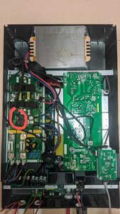
What am I doing. Resistance between the battery POS and NEG alternates from Open Loop to no resistance. Will attach video.

No warranty on this as I literally opened it out of curiosity cus I am sure this is willing to try to take my soul out of frustration.

Tried running from either single battery. I have two. No change.
Tried no AC input. No change...
Verified all connections in the inverter fed panel. Correct.
I don't know why these batteries are not feeding my inverter power... Feels like I threw almost 15-20gran away. Btw this is not a signature solar complaint. I just don't know if anyone can see what is going on. I can do a full walk through by video if anyone wants to have a go.

Edit: Will also like to add. The fuse inside the inverter battery terminal is still solid. So it's not that causing the BP as the manual states.
 
Last edited:
The rule is to always look at the simple stuff first before assuming a major problem or bad equipment. Are you sure the batteries are charged and are not shutting down on Low Voltage Cut Out?
 
The rule is to always look at the simple stuff first before assuming a major problem or bad equipment. Are you sure the batteries are charged and are not shutting down on Low Voltage Cut Out?
Batteries are 90+% 54.4v as of just now. Both checked individually.

A friend of mine is saying that these inverters are much more sensitive to faulty equipment than the grid is. So leave the fridge or whatever other I can think that may cause an issue unplugged for a few hours while checking other circuits and running on battery mode. So I'll try that tomorrow. And put the rest of the house back on utility. And move circuit by circuit and test over a 1-2 day period for each move.

I did a full rewire of the panel today just to ensure everything is correct. But not sure how to check appliances for faults.. so I'll start by process of elimination of appliances I guess tomorrow just in case.
 
If you put the inverter in SUB mode at night or with no solar input it should revert to Utility power pass through. Will the inverter run your appliances in pass through without disconnecting or shutting down?
 
If you put the inverter in SUB mode at night or with no solar input it should revert to Utility power pass through. Will the inverter run your appliances in pass through without disconnecting or shutting down?
Perfectly. everything runs fine using the bypass and grid power
 
I open the main Battery DC breaker.
I open the actual breaker on the physical battery.
technically the breakers should be closed to allow electricity to flow. It one of the areas that electricity is the opposite to plumbing.

What battery are you using?

Most of the time when connecting a battery to the inverter the Inrush will trip the short circuit protection on the battery.

Most batteries now included a precharge resistor.

So make sure you are connected to the inverter before you turn the battery on.

Alternatively. Use a resistors , or old style light bulb to bypass the nader breaker. For a few seconds before you turn it on.
Make sure the battery breaker and bms is on first.
EG4 LifePower 4 batteries BMS is internal and also have 0 errors on any battery via the BMS tools software. got them same time as the inverter.

Ah understood. Does make sense because an open circuit is one where current will NOT flow. Thank you for the knowledge.

I was under the understanding that a secondary precharge resister like a bulb etc is no longer necessary for these batteries. Also no precharge instructions in the manuals.

So yes I am allowing the voltage from the battery to reach the inverter before I flip the breakers on the battery to turn them on
Did you test the voltage at the battery terminals on the inverter?

Turning the battery on should be the last thing you do to allow the precharge resistor to work as it is only active when you for a few seconds after turning the battery on.

It could be if you have solar connected it was providing enough power to run the fan. But not the fridge.
They may be some miscommunication.. the process to power up the inverter via battery.

1. Close (using correct terminology) the main DC breaker switch.
2. Then close each battery breaker in my rack to allow power to flow to the inverter.

Flipping the individual battery breakers is the last part of the turn on process for the inverter.

For last question. Yes voltage at the terminals of the inverter with the main DC breaker for my battery bank (closed) and each battery breaker (closed). Inverter terminals show same voltage as battery terminals.

It was night and my solar breaker is off(open) to not allow DC current to run my loads. Issue here is the batteries are having issues running the loads. Yet they throw no errors. Just inverter BP disconnect.

Please send more suggestions. I'm heading to bed for now. About 9-10 hours straight going at this and need a rest. Will review every suggestion and respond to anything in a few hours.
 
Also if anyone has input. I don't believe this unit came with a bonding screw as it's a later model. Now I have grid input setup, when connected in bypass the input and output neutrals are connected thus using the main panel bond.
When the inverter is NOT in bypass now and wants to run on battery. Will this be able to create its own NG bond since the main panel bonded neutral isn't available and no physical screw to make its own?
 
The 6000EX requires 300AH in batteries to operate properly (per the manual). Sounded like you were only using one or two LP4 batteries. Two would only be 200AH, maybe that’s part of the problem causing the inverter to shut down??
 
The 6000EX requires 300AH in batteries to operate properly (per the manual). Sounded like you were only using one or two LP4 batteries. Two would only be 200AH, maybe that’s part of the problem causing the inverter to shut down??
Though the manual does say 300ah. The principle behind it still applies. Fully loaded it should only require two batteries drawing max of 125A at 48v at the inverter. Two batteries can theoretically provide 200amps based on on eg4 specs. Most my house has ever seen is 67A at 48v with my current home appliances during a test.

Also mine had never been fully loaded. So two batteries are more than enough for the 700watts it was pulling while it got the battery disconnect BP error.
 
Are you using open or closed loop communication? Try open and run off voltages if you're closed loop.
14 - USE
17 - 55.2V
18 - 54.8V
19 - 44V

03 is set to 120V, 04 is set to 60Hz, and 05 is set to BLU, correct?
 
Question which one is the bond screw for clarity. There is no info on the actual location of the bond screw available. And finally should the bond be in the system with this newest firmware than dynamically switches the bonding?

First image locations of screws.
2. Middle screw still in.
3. Lower screw out.

Reason I'm querying. I disconnected everything. Setting 34 set to ENA. I connect the output to a receptacle just to test the inverter with nothing at all. Even if my house working is messed up.

Measured at the inverter terminals I get voltage on the G. And voltage imbalance on H to G. Inverter puts out
H to G is 105 on one and 140 on the next.
G to N is 21v.
H to N is 120v and 120v on the next

Just to compare, setting program 34 to disabled results in the same voltages. But I then reverted to enabled.


I'm aging a year every day from this thing. Why is the NG not bonded at the inverter if it's running direct from battery? Or am I understanding this wrong?
PXL_20240310_083851346~2.jpg
4. Locations of the screws
PXL_20240310_083851346.jpgPXL_20240310_083833521.jpgPXL_20240310_083826630.jpg
 
Last edited:
Found a post here about it. So my screw IS installed here in red. Just confused at this point.

Location found via this thread

Edit.
How can the screw be in, program 34 allowing a NG bond while inverting from battery yet my neutral is somehow still floating while having no Grid connection...?
 

Attachments

  • PXL_20240310_083851346~3.jpg
    PXL_20240310_083851346~3.jpg
    166.9 KB · Views: 6
Last edited:
Can someone also confirm the correct method of testing for the NG bond.

Setting 34 ENA (which should be no bond in inverter) and bonded main panel with AC input.
Inverter ON with output active or off completely?
Bond screw in or out?
What are th expected range results for my multimeter for continuity?

just want to test if the internal bonding relay is working as it should with AC input in bypass and also if it's working with AC input in battery mode and still keeping this NG bond from the main panel as well.
 
Question which one is the bond screw for clarity. There is no info on the actual location of the bond screw available. And finally should the bond be in the system with this newest firmware than dynamically switches the bonding?

First image locations of screws.
2. Middle screw still in.
3. Lower screw out.

Reason I'm querying. I disconnected everything. Setting 34 set to ENA. I connect the output to a receptacle just to test the inverter with nothing at all. Even if my house working is messed up.

Measured at the inverter terminals I get voltage on the G. And voltage imbalance on H to G. Inverter puts out
H to G is 105 on one and 140 on the next.
G to N is 21v.
H to N is 120v and 120v on the next

Just to compare, setting program 34 to disabled results in the same voltages. But I then reverted to enabled.


I'm aging a year every day from this thing. Why is the NG not bonded at the inverter if it's running direct from battery? Or am I understanding this wrong?
View attachment 201262
4. Locations of the screws
View attachment 201258View attachment 201259View attachment 201260

The neutral-ground bond screw is not present on this inverter. However, I'm uncertain if this absence is related to the issue. Do you happen to know the startup draw of the refrigerator?

1710169459489.png
 
The neutral-ground bond screw is not present on this inverter. However, I'm uncertain if this absence is related to the issue. Do you happen to know the startup draw of the refrigerator?

View attachment 201454
Hi Jared. I'm actually here performing some tests that I can upload to YouTube soon. When I get my electricity back on. But good to know it's not present.

I did a test with a hair dryer. 1800w. Actually runs 1550 as reported on L2 by the inverter.

The start up of this fridge is like 800w. "Full Load rating" on the name plate is 6.5amps at 120v.

What is the make and model of the refrigerator?
 
Back
Top