diy solar

diy solar

Eg4 6000EX help

17101723887687301791690706510942.jpg

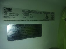
Also I have a detailed write-up that I just lost of what I tested today. Basically, I received a replacement inverter from you guys yesterday delivered evening... Almost 1000usd just to get the refurbed one here. The thing looks like it been through a way. Hole in the side. Top screws stripped. But who cares as long as it works. Also there was no certificate of why this inverter was returned or report stating it was tested before shipment.. I thought that would have been almost required but...anyways.

I opened it. Warranty is out the window anyway. There is also no screw based on the location you quoted. No problem.

I attempted to set up as off grid just to test. No grid input on any of those terminals. From my understanding the program 34 set to ENA means it enables the bypass relay and allows NG bond from a main panel to pass through IF grid is detected. If grid is not detected the relay should create its own and bond at the inverter even without a bond screw.

Now my tests for this seem inconclusive. I have the new inverter bench setup just batteries and output terminals. 34 to ENA.

H2 to N 133v.
H1 to N 108v
G to N 14v.
H2 or H1 to N 120v.

Does this indicate the bond in the inverter is not present as I have current on my Ground?


Also did a subsequent test to detect what change would be if Program 34 Disabled. No change...
H2 to N 140v.
H1 to N 106v
G to N 420v.
H2 or H1 to N 120v

Now onto the next issue which my original inverter was having the same issue with. This refurb one does the exact same thing. Barely 18 cycles on the batteries in total since August last year!

I set up the grid input as neither of the inverters handle the bond correctly it seems.(I am subject to correction on this based on my previous test)
With 34 Enabled, grid input(bonded main panel) H1, H2, N and G into the input terminals of the inverter. I finally get the pass through bond and proper voltages on inverter output terminals.
H1 to N 120v
H2 to N 120v
H1 to G 120v
H2 to G 120v
N to G 0.4 or less volts
But continuity N to G is like 150ohms. Shouldn't it be full continuity like 0.0x resistance value? (Correct me if I'm wrong or 150 ish ohms is acceptable on the output)

Now im not going to run the fridge as that is pretty important. I used a hair dryer 1875w rating, actually pulling 1.56kw. Should be able to easily handle that on one leg.

The hair dryer runs for undetermined amounts of minutes then BP battery disconnect error. SAME error I was getting with previous inverter. I have BMS tools open and monitoring the batteries there was no under volt or over current faults recorded. Just BP on inverter.

BMS tools reported 89/90% at start of the test so it's impossible it can undervolt a battery that was reporting 52ish volts and if it did. It should have occurred at the start. So is it possible this inverte has the same issue?

Two. I tried this on both batteries in parallel. Also individually just to see if one battery was causing the issue. Nothing. I borrowed a growatt inverter 6k and the batteries pull from it fine without issue.

Sorry for the long winded information but. This is crazy. Again. Tell me if I missed anything at all here please.
 
View attachment 201469

Also I have a detailed write-up that I just lost of what I tested today. Basically, I received a replacement inverter from you guys yesterday delivered evening... Almost 1000usd just to get the refurbed one here. The thing looks like it been through a way. Hole in the side. Top screws stripped. But who cares as long as it works. Also there was no certificate of why this inverter was returned or report stating it was tested before shipment.. I thought that would have been almost required but...anyways.

I opened it. Warranty is out the window anyway. There is also no screw based on the location you quoted. No problem.

I attempted to set up as off grid just to test. No grid input on any of those terminals. From my understanding the program 34 set to ENA means it enables the bypass relay and allows NG bond from a main panel to pass through IF grid is detected. If grid is not detected the relay should create its own and bond at the inverter even without a bond screw.

Now my tests for this seem inconclusive. I have the new inverter bench setup just batteries and output terminals. 34 to ENA.

H2 to N 133v.
H1 to N 108v
G to N 14v.
H2 or H1 to N 120v.

Does this indicate the bond in the inverter is not present as I have current on my Ground?


Also did a subsequent test to detect what change would be if Program 34 Disabled. No change...
H2 to N 140v.
H1 to N 106v
G to N 420v.
H2 or H1 to N 120v

Now onto the next issue which my original inverter was having the same issue with. This refurb one does the exact same thing. Barely 18 cycles on the batteries in total since August last year!

I set up the grid input as neither of the inverters handle the bond correctly it seems.(I am subject to correction on this based on my previous test)
With 34 Enabled, grid input(bonded main panel) H1, H2, N and G into the input terminals of the inverter. I finally get the pass through bond and proper voltages on inverter output terminals.
H1 to N 120v
H2 to N 120v
H1 to G 120v
H2 to G 120v
N to G 0.4 or less volts
But continuity N to G is like 150ohms. Shouldn't it be full continuity like 0.0x resistance value? (Correct me if I'm wrong or 150 ish ohms is acceptable on the output)

Now im not going to run the fridge as that is pretty important. I used a hair dryer 1875w rating, actually pulling 1.56kw. Should be able to easily handle that on one leg.

The hair dryer runs for undetermined amounts of minutes then BP battery disconnect error. SAME error I was getting with previous inverter. I have BMS tools open and monitoring the batteries there was no under volt or over current faults recorded. Just BP on inverter.

BMS tools reported 89/90% at start of the test so it's impossible it can undervolt a battery that was reporting 52ish volts and if it did. It should have occurred at the start. So is it possible this inverte has the same issue?

Two. I tried this on both batteries in parallel. Also individually just to see if one battery was causing the issue. Nothing. I borrowed a growatt inverter 6k and the batteries pull from it fine without issue.

Sorry for the long winded information but. This is crazy. Again. Tell me if I missed anything at all here please.

Just to confirm, this also happens when the refrigerator is the only thing trying to be powered?
 
Just to confirm, this also happens when the refrigerator is the only thing trying to be powered?
Yes. Sorry for late reply. Was just placing everything back over on the grid pass through. As that's the only thing that reliably works, albeit I can not run on battery. Basically SUB. But without the reliability of the battery. So if grid goes down. I also go down because battery mode will not run anything.
 
Are you running in voltage mode for lead acid or do you have the BMS hooked up and properly reporting the SOC?
 
As it came from signature. I also tested with the comm cable to first battery. Inverter set to EG4 and the default 10% 0% shut down, 30% 10 %switch to grid. It's on latest firmware so it doesn't use voltages anymore it's SoC. Also tried in User mode with my defined voltages for Low Voltage Cut off etc etc.

This video is still processing. I no alarms on the battery and the invert voltage battery voltage only dips when it disconnects itself from the battery (or the battery disconnects itself from the inverter).

But it doesn't seem like low voltage cut off is being hit.

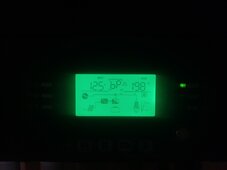
This is the fridge running only on that entire leg. 198w. After being off for about 4 hours because I was working on it. I had some kill-o-watt with min and max readings with the fridge but I would have to find them if I can. But i can say this fridge never goes above 800 any time. Even auto defrosting the freezer.

Finally link is ready.
 

Attachments

  • 17101780077712906517733554510596.jpg
    17101780077712906517733554510596.jpg
    46.7 KB · Views: 1
Last edited:
Are you running in voltage mode for lead acid or do you have the BMS hooked up and properly reporting the SOC?
Sorry missed this part. Lithium not lead acid. And always using using BMS % but also tried voltages under User.
 
If anyone can add. What would the values be when set to EG4 BMS comms. I know 10% etc. but what are those in actual voltage values. I have to consider it as well even though I looked at it before. Again. Not saying i have it correct. But I'm here asking for allll possible options. So everyone if you can. Throw any idea I'll look at it
 
Found a post here about it. So my screw IS installed here in red. Just confused at this point.

Location found via this thread

Edit.
How can the screw be in, program 34 allowing a NG bond while inverting from battery yet my neutral is somehow still floating while having no Grid connection...?
Also. That thread EG4 Jarrett says another screw is the bond screw(the board on left immediately behind the removable cover).. yet you're (Jared) saying a different screw is(one on the main board on the back of the inverter)
That's very conflicting information if Im reading right. Someone may take out a useful screw for operation.
 
New issue.. or compounding issue.

I have output connected. Breaker off.
Input connected or disconnect this test was the same.

I run from battery only. No solar. And this happens the battery terminal on the inside of the inverter starts arcing either the terminal or just behind it. Then it hits BP battery disconnected error on the inverter. Batteries show no error. I'm really not sure.


17102488465273620903748575392549.jpg
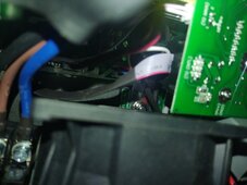
That terminal just behind the fan with the red marking. The arcing/popping is coming from that.

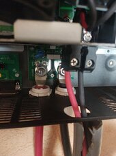
In case anyone wants to see again my connections.
Batteries 90% ish 52v.

17102490456284787209627482620617.jpg
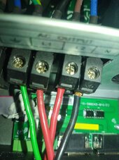
Output connections. N is actually in securely and fully. Strip was just a bit long with all the testing.

This is a new(refurb unit doing it)

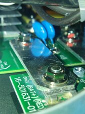
This is the area that's arcing. On the battery terminal inside the inverter. After turning on main breaker between battery and inverter then turning on each battery. Upon powering up just ticking. I shut back down now cus I'm frustrated...I don't even get to the stage to output power to the house now. I did hear this once before the very first time but I think I dismissed it because it never came up again.

17102493523691172224438277038507.jpg

This appears to be the board and terminal that's arcing..or just around the nut and behind it. Board looks a bit discoloured also. What would cause this to happen?
 

Attachments

  • 17102489254313275378879258091499.jpg
    17102489254313275378879258091499.jpg
    139.3 KB · Views: 4
Last edited:
Thank you @420hmsPA I'll get some eyes on it too. Don't give up @Quankl - I know you said this is not a complaint about us, but to confirm, did you get it from Signature Solar? If there is anything we can do, we'd love to help. You can DM me your order number and I can have a look into if there's anything we can do to get you back up and running.
 
This is a refurbished unit that I just got. Both from signature. Will send you the details in a two or so hours. Stepped out to clear mind.
 
New issue.. or compounding issue.

I have output connected. Breaker off.
Input connected or disconnect this test was the same.

I run from battery only. No solar. And this happens the battery terminal on the inside of the inverter starts arcing either the terminal or just behind it. Then it hits BP battery disconnected error on the inverter. Batteries show no error. I'm really not sure.


View attachment 201658
That terminal just behind the fan with the red marking. The arcing/popping is coming from that.

In case anyone wants to see again my connections.
Batteries 90% ish 52v.

View attachment 201661
Output connections. N is actually in securely and fully. Strip was just a bit long with all the testing.

This is a new(refurb unit doing it)

This is the area that's arcing. On the battery terminal inside the inverter. After turning on main breaker between battery and inverter then turning on each battery. Upon powering up just ticking. I shut back down now cus I'm frustrated...I don't even get to the stage to output power to the house now. I did hear this once before the very first time but I think I dismissed it because it never came up again.

View attachment 201664

This appears to be the board and terminal that's arcing..or just around the nut and behind it. Board looks a bit discoloured also. What would cause this to happen?

Does the last image look like the jumper is fused (melted) just under the nut. And should that be so? What would cause excessive heat like this inside the inverter?

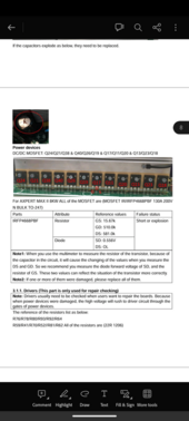
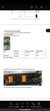
Also what is the purpose of the F3 fuse just above the battery terminals. What is the correct way to test that with the multimeter other than removing and continuity.

Will have a look at these parts today/tomorrow and check for damage.
 

Attachments

  • Screenshot_20240313-064450_Adobe_Acrobat.png
    Screenshot_20240313-064450_Adobe_Acrobat.png
    273.6 KB · Views: 7
  • Screenshot_20240313-064443_Adobe_Acrobat.png
    Screenshot_20240313-064443_Adobe_Acrobat.png
    210.7 KB · Views: 7
Last edited:
Systems running perfect for last two days/nights. Pulling ALL loads. Don't even have to use my grid input anymore for the battery drop outs.

Been on pass through for the last 6 or so months because of the issue.

The good:

I went through the RMA process for the EG4 6000EX. They took a while but my case was out of the ordinary. They went beyond the call of duty for a replacement because I am not in the US. Thousands of miles away actually, albeit it took a long time.

The bad:

1. First of all the replacement unit had the same exact issue my original had. Yes. It did. I was dumbfounded when I connected everything.
2. The refurb/replacement unit was beat up as shit with a hole cut in the side for whatever reason, I don't know but it functions as it should.
3. The issue was very simple but critical... All nuts inside both units were slack and causing arcing, Battery disconnects(BP), and dropped loads and trying to bypass to grid to keep the loads running. Quality control is not there and it's dangerous when having things running up to 240v.


The verdict. This system 6000EX in my opinion seems like a good system in theory but was a bad system from the factory. Possibly why they stopped selling them. But if anyone has the same issues. I encourage you to quickly contact them, request to open the inverter under warranty and move everything out the way and tighten EVERYTHING before something had happens.

But all in all. I think there are people at signature who really try to do their best and I'm sure they can't openly say "This product was not our best choice to sell to customers". Point is they did, they realised it had issues, they stopped selling it and trying to correct. What they should do is replace all these units with 6000XPs when persons contact with legitimate RMA requests instead of sending problematic units back out or even request that we can upgrade you for an small upgrade fee instead.

Those persons who helped me from all last year to right now. Really appreciate the help.
@BenFromSignatureSolar
@SignatureSolarJess
@Travis_signaturesolar
@EG4_Jared
And the forum members here.
RMA team lady that I spoke to numerous times(can't remember her name)

But. Those with 6000EXs with similar problems to my post history. Please just check your internet nuts to make sure they are torqued firmly.
 
Last edited:
Back
Top