diy solar

diy solar

EG4 6000XP/18Kpv Custom RS485 Dongle Connector

Can somebody point me to the rs485 connector on the 6000xp? it doesn't look like the board diagram above which must be the 18kpv. The board has this green on white lettering referencing P1 and P2 but which of the RJ45 plugs is it talking about? Surely not BatCom or you couldn't also talk to your batteries. Surely not the parallel ports for inter-inverter communication.. The manual references "these two pins" but doesn't say which ones.


View attachment 214350 View attachment 214349
I’m not sure if it’s referencing the top two ports or not.

The “pins” it’s talking about are P1 and 2. Pin 1 on the RJ45 is rs485A and Pin 2 is rs485B.

I know the BattCom can use Rs485.
 
This post by @marionw seems to suggest the rs485 pins to interrogate the inverter itself are in fact in the battery comms jack. I guess I'll give that a try unless anyone else knows for sure? And does the modbus address have to be set by modbus command? I found a post where it is accessible via the front display on the 18kpv but I can't find any such setting on the 6000xp
 
Last edited:
This post by @marionw seems to suggest the rs495 pins are in fact in the battery comms jack. I guess I'll give that a try unless anyone else knows for sure? And does the modbus address have to be set by modbus command? I found a post where it is accessible via the front display on the 18kpv but I can't find any such setting on the 6000xp
I’m not aware of any place in the UI/monitoring site for the 6000xp where you can set a Modbus address.
 
Can somebody point me to the rs485 connector on the 6000xp? it doesn't look like the board diagram above which must be the 18kpv. The board has this green on white lettering referencing P1 and P2 but which of the RJ45 plugs is it talking about? Surely not BatCom or you couldn't also talk to your batteries. Surely not the parallel ports for inter-inverter communication.. The manual references "these two pins" but doesn't say which ones.


View attachment 214350 View attachment 214349
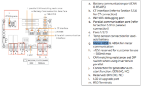
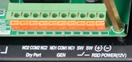
Sorry, it's not in the 6000XP manual, what are those push-in terminals on the lower right of your picture? In the 18Kpv it's a terminal block below the RJ45 connectors (see g. below):Screenshot 2024-05-10 at 6.50.31 AM.png
 
Do you even know if you are supposed to have an RS485 meter port?
yes according to section 8.2 above of the manual and the 6000xp modbus manual it has modbus over rs485... they just did a poor job in the manual of explaining where the physical interface is. And it would have been much better to provide direct terminal blocks like the 18kpv vs expecting us to splice it into an rj45 somewhere.
 
yes according to section 8.2 above of the manual and the 6000xp modbus manual it has modbus over rs485... they just did a poor job in the manual of explaining where the physical interface is. And it would have been much better to provide direct terminal blocks like the 18kpv vs expecting us to splice it into an rj45 somewhere.
Does it use the same WiFi interface dongle? If so, look for a recent thread on an HDMI(*) to USB interface someone’s roommate was trying to productize.
(*) Yes, they use an HDMI connector. 🤷‍♂️
You won’t be able to use the WiFi dongle at the same time as the adapter, so be aware of that.
 
I have not yet had a chance to try, but the meter ports (with the plastic plugs) should be on the main rs485 bus.
 
(g) works fine.
What software are you using to talk to it? I've built something very basic in Python with MinimalModbus that returns some numbers, so I'm pretty sure I have the port (/dev/ttyACM0) and baud rate (19200) right, but the numbers I'm getting don't make any sense, and HotNoob's PythonProtocolGateway crashes. I'm clearly doing something wrong!
 

diy solar

diy solar
Back
Top