diy solar

diy solar

EG4 6000XP and SolarAssistant

jsmithtx

New Member
Joined
Dec 28, 2023
Messages
99
Location
Dallas, TX
It does not appear SolarAssistant works with the EG4 6000XP inverter and EG4 batteries an truly offline manner.

Has anyone successfully got this inverter communicating with SA *without network*? I saw something in the manual about a meter1/2 (page 25) but every wire pair I tried would not connect. I'm also curious if anyone has tried the BMS communication with SA *while retaining BMS communication with the inverter*. Curious @EG4_Jarrett what the appropriate meters are coming out of that area (7.2, p. 25). I see 4 wires -- red, blue, white, black. Which one is + and which is - for RS485? "Meters 485B and 485A can be used when a meter is not connected.These two pins can be used to communicate with the inverter using the RS485 Modbus protocol."
 
Last edited:
So network and internet are different. Not suggesting you didn’t know that but Luxpower only works through a Wireless connection to SA. You will need a network but not necessarily internet traffic available.
 
It does not appear SolarAssistant works with the EG4 6000XP inverter and EG4 batteries an truly offline manner.

Has anyone successfully got this inverter communicating with SA *without network*? I saw something in the manual about a meter1/2 (page 25) but every wire pair I tried would not connect. I'm also curious if anyone has tried the BMS communication with SA *while retaining BMS communication with the inverter*. Curious @EG4_Jarrett what the appropriate meters are coming out of that area (7.2, p. 25). I see 4 wires -- red, blue, white, black. Which one is + and which is - for RS485? "Meters 485B and 485A can be used when a meter is not connected.These two pins can be used to communicate with the inverter using the RS485 Modbus protocol."
Sorry, I didn't see the tag in my notifications or I would have responded sooner.

I haven't played around with any of the 3rd party stuff yet, so I don't know right off the top of my head, but I will do some research and see what I can find out!
 
It does not appear SolarAssistant works with the EG4 6000XP inverter and EG4 batteries an truly offline manner.

Has anyone successfully got this inverter communicating with SA *without network*?
Setup a wifi network that's not connected to the internet. Connected your Pi and 6000XP to that network.
 
Do you have EG4 LL or EG4 Lifepower batteries? The batteries have different communication ports.
The EG4 hub may solve the issue depending on how the EG4 LL "master" battery (the one set to address 1) communicates to the other batteries.
In the video above EG4 Lifepower4 batteries are being used and the hub will work to get the inverter, the batteries and Solar Assistant working as this is what I am using. You will just need to make sure you get the correct cables for SA to communicate with the inverter and the batteries.
Looking at @jsmithtx older post, OP purchased LL-S batteries.

@jsmithtx The video posted above used Lifepower4 batteries, not the LL-S.
 
In the video above EG4 Lifepower4 batteries are being used and the hub will work to get the inverter, the batteries and Solar Assistant working as this is what I am using. You will just need to make sure you get the correct cables for SA to communicate with the inverter and the batteries.
I'm curious about this...I have an EG4 6000ex, LifePower4 batteries and the communication hub. Did you use the battery cable that came with your batteries to connect SA? I was told by SA support that you couldn't use it with the hub and AIO since setting the first battery DIP to 1 changes the protocol.
 
I'm curious about this...I have an EG4 6000ex, LifePower4 batteries and the communication hub. Did you use the battery cable that came with your batteries to connect SA? I was told by SA support that you couldn't use it with the hub and AIO since setting the first battery DIP to 1 changes the protocol.
6000EX and 6000XP are different inverters.

I never tested the Hub with my 6500ex.

In the video the battery DIPs are 1-12 with firmware v3.32. The Hub is connected to battery 1. Battery 12 is connected to SA through the Read/Write firmware cable that came with the battery.
 
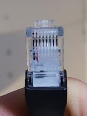
The AIO is connected to the "Inv" port on the hub and the protocol for this port is selectable to match the AIO protocl. The hub acts the same as a Lifepower4 battery set to address 0. The hub communicates with the batteries on pins 7&8 of the hub (Bat port) to pins 7&8 on the RJ45 jack on the batteries. SA needs to use pins 1&2 of the jacks. Both jacks on the Lifepower4 batteries parallel pins 1&2 on one jack with pins 1&2 on the other, pins 7&8 are also wired in parallel. This creates two RS485 buses with the hub using the pins 7&8 bus. SA or a computer (not both at the same time) will run on the pins 1&2 bus to monitor the batteries. The RS485 to USB cable needs to have pins 1&2 of the RJ45 connector connected to the USB converter. If the cable uses pins 7&8 (or any other pins except 1&2) SA will have issues. I don't know what pins the read/write cable uses, maybe by eyeballing the RJ45 connector you can tell. While holding teh connector with the locking tab down/away from you and the pins up and facing you, pins 1&2 with be the left most pins and pins 7&8 will be the right most pins
 
The AIO is connected to the "Inv" port on the hub and the protocol for this port is selectable to match the AIO protocl. The hub acts the same as a Lifepower4 battery set to address 0. The hub communicates with the batteries on pins 7&8 of the hub (Bat port) to pins 7&8 on the RJ45 jack on the batteries. SA needs to use pins 1&2 of the jacks. Both jacks on the Lifepower4 batteries parallel pins 1&2 on one jack with pins 1&2 on the other, pins 7&8 are also wired in parallel. This creates two RS485 buses with the hub using the pins 7&8 bus. SA or a computer (not both at the same time) will run on the pins 1&2 bus to monitor the batteries. The RS485 to USB cable needs to have pins 1&2 of the RJ45 connector connected to the USB converter. If the cable uses pins 7&8 (or any other pins except 1&2) SA will have issues. I don't know what pins the read/write cable uses, maybe by eyeballing the RJ45 connector you can tell. While holding teh connector with the locking tab down/away from you and the pins up and facing you, pins 1&2 with be the left most pins and pins 7&8 will be the right most pins
20240111_145911.jpg
 
The above cable looks right. Test by plugging into a computer and running the BMS_Tools software. If you can talk to the batteries with the tool then SA should be able to as well. You need the select to correct port for the batteries on the SA configuration tab. Once selected, and you click the "Connect" button you should see SA start scanning for batteries, it will skip 0, and will indicate when it finds a battery and once it tests for a battery that does not respond (other than 0) it will stop scanning so if you have a gap in addresses it will miss the batteries after the gap
 
Last edited:
Setup a wifi network that's not connected to the internet. Connected your Pi and 6000XP to that network.
This is what I do NOT want to do. I want hardwired only.

"Meters 485B and 485A can be used when a meter is not connected. These two pins can be used to communicate with the inverter using the RS485 Modbus protocol." (7.2)

The docs suggest I could wire into the inverter for communication. I would like to go this route, rather than wifi.
Buy the Ethernet adapter.
 
Buy the Ethernet adapter.
I wondered about that.

And it does work with 6000px: https://eg4electronics.com/categories/communication/wlan-ethernet-adapter
 
I get what you are saying. I do not want my data under anyone elses control. What are the two ports above the BMS and Parallel ports used for? I could not find any documentation or pinout description for them
 
I think some BMS have 2 buses but 1 is read/write for programming and the other is read only meant for the inverter.
Some have an RS232 port for programming, sometimes separate and sometimes built into the RS485 port.
 
Now for the next question. How does one get Solar Assistant to work with the EG4 LL-S batteries while keeping them connected to the inverter? The LL-S has two ethernet plugs above the battery terminal (and two below); currently the CAN port goes to the inverter. When I plug the RS485 one into SS, the inverter kills the power.

1. CAN ---> to inverter
2. RS485 (plugging SS in here causes inverter to kill power)
3. Battery Comm
4. Battery Comm --> to next battery

Where should SS be plugged in at?
Can you elaborate on inverter kill power? Does the LLS Breaker turn off?

What PINs are you using for the RS485? I think LL-S PIN 8 is used to trip the battery RSD.
 
Back
Top