diy solar

diy solar

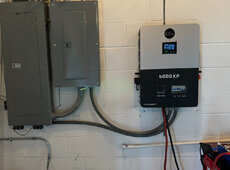
Eg4 6000xp

Pass through is rates at 50 amps per leg. Psst the breakers are actually rated for 63 amps. (I have no idea what the relay is rated for) side note 63 x 80% = 50

No the inverter will not allow an AC grid connection on a single 120v leg...I don't recommend bridging L1 with L2.
Great news regarding the pass thru. I've had 4 separate people at Signature Solar tell me the grid pass thru limit is limited to 3000W on each leg. Sounds like you and @AZ Solar Junkie above have both tested it first hand. Thank you!!!!
 
Last edited:
Great news regarding the pass thru. I've had 4 separate people at Signature Solar tell me the grid pass thru limit is limited to 3000W on each leg. Sounds like you and @AZ Solar Junkie above have both tested it first hand. Thanks you!!!!
Yeah I don’t know what someone was smoking. It’s clear even in the specs in the manual…
 

I don’t recommend this inverter in an RV whatsoever. Furthermore it cannot accept just 120v input - it must be split phase 120/240
 
I haven't seen anything posted on the AC grid feed to the inverter and the manual isn't clear. What size breaker is needed in the main panel: 40a or 50a?
 
Thanks, @ChrisG and @AZ Solar Junkie. That's what I thought. Going to replace a 6000ex with the 6000xp, currently using a 40a breaker. Looks like another part of the upgrade.
I just installed mine. Bought two 50a breakers one for main panel and one for critical loads. Think I got them both for $32.
 

Attachments

  • IMG_4593.jpeg
    IMG_4593.jpeg
    929.1 KB · Views: 15
50a and 8awg thhn wire.
Utilizing 8 AWG copper and 6 AWG aluminum conductors is generally not recommended, even though they fall within the 50 AMP to 60 AMP capacity range. This is because, as per the National Electrical Code (NEC), the maximum operational load of an electrical circuit shouldn’t surpass 80% of its capacity. 6 AWG copper is the recommended wire size for a 50 amp circuit.
 
Utilizing 8 AWG copper and 6 AWG aluminum conductors is generally not recommended, even though they fall within the 50 AMP to 60 AMP capacity range. This is because, as per the National Electrical Code (NEC), the maximum operational load of an electrical circuit shouldn’t surpass 80% of its capacity. 6 AWG copper is the recommended wire size for a 50 amp circuit.
Hmm. Doesn’t say that in the manual, I’m using 10ft of 8awg copper thhn for each run. I’ll never have 12k passthrough anyway, don’t have the loads to support it in sub panel. Would have gotten a larger inverter if that was the case. Guess to be compliant I could downgrade the breakers to 40a.
 
Hmm. Doesn’t say that in the manual, I’m using 10ft of 8awg copper thhn for each run. I’ll never have 12k passthrough anyway, don’t have the loads to support it in sub panel. Would have gotten a larger inverter if that was the case. Guess to be compliant I could downgrade the breakers to 40a.
Yeah if your loads aren’t going to be demanding the 50 amps of bypass you should be fine eh. Downgrading the breakers is a good idea though to protect the 8 gauge wire… every situation is unique.
 
Out of curiosity, looking at the specification, it appears the 6000XP has an AC input limit of 37.5amps (9000W). So I can account for the 25amps (6000W) going to the loads with the remaining 12.5amps (3000W) charging the battery. So how does one make use of the remaining 12.5amps (3000W) of the 50 amp by-pass specification?

Is this a buffer for intended overload operation?
When it’s in bypass mode, it can pull up to 50 amps and pass them directly to the loads, minus any power being used for charging the batteries. If you’re not charging batteries either because they are full or AC charging is disabled, the full 50 amps could go to the loads.
 
When it’s in bypass mode, it can pull up to 50 amps and pass them directly to the loads, minus any power being used for charging the batteries. If you’re not charging batteries either because they are full or AC charging is disabled, the full 50 amps could go to the loads.
@AZSolarJunkie, Thanks for your assessment of the 50amp bypass, I follow and agree.

However, my curiosity is more focused on how a home system could be designed to make use of the full 50amp by-pass. While being limited to the 37.5amp AC IN specification. I feel I'm still mis-understanding something.
As far as I understand, the 37.5 amp input limit is only when it is NOT in bypass…
 
As far as I understand, the 37.5 amp input limit is only when it is NOT in bypass…
Ok got it...thanks!

So then, now I can see why the 6000XP bypass spec its at 50A. It assumes you can charge your batteries while running the rated load.

Bypass current budget (if you'll allow me this term):
  • 25amps (3000w) for running the load while in "bypass mode".
  • 25amps for charging the battery while the inverter is in "bypass mode".
    • Spec: **115A @ 48Vdc
      • AC Input charging watts = (115v x 48v) / 93% efficiency spec. = 5,935.4 watts
      • AC Input charging current = 5,935.4 watts / 240v = 24.7amps or simply 25 amps
👍🏻 Except if your batteries are full or AC charging is disabled, all 50 amps of bypass would be available to pass on to the loads.
 
Have (2) questions related to EG4 6000XP and EG4 LL-S 48V battery.
----
(1) What size cable size from inverter to batter - 1 AWG or 2 AWG?

System will have (2) EG4 LL-S batteries and expand to (4) at some point.

The manual for the EG4 6000XP recommends a 1 AWG cable to connect to battery terminal but the EG4 LL-S manual recommends a 2 AWG cable to connect battery terminal. Seems like many simply recommend going with 2AWG wire.

EG4 6000XP Manual (p.15) - https://eg4electronics.com/backend/wp-content/uploads/2023/10/EG4-6000XP-Manual.pdf
EG4 LL-S Manual (p. 12) - https://eg4electronics.com/backend/wp-content/uploads/2023/09/EG4-LL-S-48V-100AH-Manual.pdf
------
(2) What cable size for connecting battery to battery?

EG4 LL-S come with 6 AWG cable to connect battery to server rack but no mention, that I found, related to battery to battery.


😎Thanks!
 
Last edited:
Have (2) questions related to EG4 6000XP and EG4 LL-S 48V battery.
----
(1) What size cable size from inverter to batter - 1 AWG or 2 AWG?

System will have (2) EG4 LL-S batteries and expand to (4) at some point.

The manual for the EG4 6000XP recommends a 1 AWG cable to connect to battery terminal but the EG4 LL-S manual recommends a 2 AWG cable to connect battery terminal. Seems like many simply recommend going with 2AWG wire.

EG4 6000XP Manual (p.15) - https://eg4electronics.com/backend/wp-content/uploads/2023/10/EG4-6000XP-Manual.pdf
EG4 LL-S Manual (p. 12) - https://eg4electronics.com/backend/wp-content/uploads/2023/09/EG4-LL-S-48V-100AH-Manual.pdf
------
(2) What cable size for connecting battery to battery?

EG4 LL-S come with 6 AWG cable to connect battery to server rack but no mention, that I found, related to battery to battery.


😎Thanks!
Will you be using the battery rack with the integrated bus bars?

Like the battery manual says, the 2 AWG recommendation is for the up to 100 amp continuous output of a single battery. The 6000xp can pull up to 125 amps continuous when putting out its max of 6000 watts, which is why it recommends 1 AWG.

The short 6 AWG cables are meant to connect each battery to the bus bars in the battery cabinet. I know some people use them to connect the batteries directly together, but they’re intended for connecting each battery to shared bus bars. Then you can use 1 AWG to connect the 6000xp to the bus bars.
No battery rack.
 
No battery rack.
In that case just get some bus bars to connect the batteries to and then connect the inverter to the bus bars with 1 AWG. With only 2 batteries it wouldn’t be difficult to connect them both to the bus bars with the short 6 AWG cables, but when you get to 4 batteries you will probably need some longer cables for all the batteries to be able to reach the bus bars. It’s recommended that all the batteries use the same cable lengths to the bus bars.

There are entire threads about people’s recommendations on bus bars. Popular options seem to be the Victron Lynx and the Bluesea bus bars.
 
Have (2) questions related to EG4 6000XP and EG4 LL-S 48V battery.
----
(1) What size cable size from inverter to batter - 1 AWG or 2 AWG?

System will have (2) EG4 LL-S batteries and expand to (4) at some point.

The manual for the EG4 6000XP recommends a 1 AWG cable to connect to battery terminal but the EG4 LL-S manual recommends a 2 AWG cable to connect battery terminal. Seems like many simply recommend going with 2AWG wire.

EG4 6000XP Manual (p.15) - https://eg4electronics.com/backend/wp-content/uploads/2023/10/EG4-6000XP-Manual.pdf
EG4 LL-S Manual (p. 12) - https://eg4electronics.com/backend/wp-content/uploads/2023/09/EG4-LL-S-48V-100AH-Manual.pdf
------
(2) What cable size for connecting battery to battery?

EG4 LL-S come with 6 AWG cable to connect battery to server rack but no mention, that I found, related to battery to battery.


😎Thanks!
Just another view for a worst case perspective:

Looking at the 6000XP output capabilities both peak and continuous. And figuring the needed battery power after factoring the efficiencies of 6000XP;

6000XP Output (W) / Efficiency = Need Battery Power (W)

6000W (continuous) / 0.93 = 6,452 watts of battery (continuous)

11,000W (5 sec) / 0.93 = 11,827 watts of battery (5 sec)

12,000W (3.5 sec) / 0.93 = 12,903 watts (3.5 sec)


Inverter to Battery Server Rack:

This yields a worst case battery current between 6000XP inverter and two EG4-LL-S batteries both peak and continuous;

Battery(W) / Lowest Battery Voltage = Battery (Amps) worst case

Continuous: 6,452W / 48V = 134.4 Amps => 4 AWG NEC 2020 Table 310.17 (Free Air)

Peak 5 sec: 11,827W / 48V = 246.5 Amps => 1/0 AWG NEC 2020 Table 310.17 (Free Air)

Peak 3.5 sec: 12,903W / 48V = 268.8 Amps => 2/0 AWG NEC 2020 Table 310.17 (Free Air)

Note: Note while using two EG4-LL-S batteries you may not have the ability to meet the peaks demands of the 6000XP. This may not be a problem depending upon the demands of your load.

Comments: I would recommend the 2/0 AWG wire between the battery server rack and 6000XP inverter. Yes, it’s a little more expensive but it’s a short run. This would allow for an acceptable level of heating (per NEC 2020) within the wiring during peak operation of the 6000XP inverter.


Battery to Server Rack Cable size:

Assuming the two EG4-LL-S batteries are in a server rack utilizing the buss bars. The 6 AWG wire that comes with the battery is almost adequate per NEC 2020 Table 310.17 (Free Air) but you may want to consider another battery so that three batteries share the peak demand.

6 AWG -> 105 amps => assuming 90 degree C, THHN or USE-2, Free Air, per NEC 2020 Table 310.17

4 AWG -> 140 amps => assuming 90 degree C, THHN or USE-2, Free Air, per NEC 2020 Table 310.17

Two sets of 6 AWG wires connecting two batteries to buss bars within server rack allows for 210 amps of wire capacity to the inverter. This is ok for continuous however during peak time you may generate a little heat on your cables.

When you add a third battery your wire capacity allows for 315 amps to the inverter. This arrangement would meet the demand of the 6000XP inverter. However, if two batteries are all you have at the moment, then 4 AWG wires will give you a 280 amp capacity to meet the peak demands of the inverter.

Hope this helps
Those short peaks of surge power though don't require heavier gauge wire necessarily. The NEC recommendations for wire gauge amps is for continuous power. Short surges of higher amps should be fine. Still, heavier wire is always better ;) I do 2/0 from the rack bus bars to a lynx power in, and 1/0 from the lynx to each inverter. Using the short 6 awg wires from each battery to the rack bus bar I've never seen them get warm at all even during surge demand...
 
Have (2) questions related to EG4 6000XP and EG4 LL-S 48V battery.
----
(1) What size cable size from inverter to batter - 1 AWG or 2 AWG?

System will have (2) EG4 LL-S batteries and expand to (4) at some point.

The manual for the EG4 6000XP recommends a 1 AWG cable to connect to battery terminal but the EG4 LL-S manual recommends a 2 AWG cable to connect battery terminal. Seems like many simply recommend going with 2AWG wire.

EG4 6000XP Manual (p.15) - https://eg4electronics.com/backend/wp-content/uploads/2023/10/EG4-6000XP-Manual.pdf
EG4 LL-S Manual (p. 12) - https://eg4electronics.com/backend/wp-content/uploads/2023/09/EG4-LL-S-48V-100AH-Manual.pdf
------
(2) What cable size for connecting battery to battery?

EG4 LL-S come with 6 AWG cable to connect battery to server rack but no mention, that I found, related to battery to battery.


😎Thanks!
@HighCountry

Created four drawings showing your potential configurations based upon using buss bars or no buss bars as well as 2 batteries versus 3 or more batteries.

When using two EG4-LL-S batteries with the 6000XP, the capacity of the two EG4-LL-S batteries becomes fully utilized under peak conditions. So… when you get a handle on your specific loading of 6000XP, you can determine if there is any urgency of obtaining a 3rd battery.

These wires sizes are based off the NEC 2020 Table 310.17 (Per EG4-LL-S page 13 manual).

So back to the two-battery configuration. After looking at the battery specifications, it appears the two EG4-LL-S batteries may be able to support the 6000XP under peak surge conditions of 12,000W @268.8 amps for 3.5sec. In practice, I have not verified this surge condition. I suspect it based upon the BMS reaction to the surge versus the battery cells.

This is why if there is a chance the two-battery configuration can deliver the surge demand. Then the recommended 4 AWG wire would additionally be less resistive in the effort to support the surge over the 6AWG wire delivered with the battery.

If however, the two EG4-LL-S batteries cannot deliver the 6000XP 268.8 amps surge then your system would need 3 batteries to support the 6000XP surge requirements and now the 6AWG wire becomes the recommend wire size in a buss bar configuration (per NEC2020 Table 310.17).

The calculations in these drawings can be found in my previous post#48.

Hope this helps.

Drawings:
1710704988745.png
 

diy solar

diy solar
Back
Top