


You are using an out of date browser. It may not display this or other websites correctly.
You should upgrade or use an alternative browser.
You should upgrade or use an alternative browser.
Eg4 6500 and new panels
- Thread starter vriosiii
- Start date
EastTexCowboy
Solar Wizard
You should be okay to do it either way.
6 x 37v = 222v which is well under the 500v cap on the 6500
If you combine the two strings parallel you'll still have 222v but will double the amps, but you're within range for that as well - 8.78 x 2 = 17.56a. I want to say the cap on amps with the 6500 is 18 amps so you're right there, but it should work fine.
Personally I'd run two strings then the amps are lower and you're never going to have a problem with overload. Plus if you get shading on one it won't affect the other. But as with all things solar, it depends. How are away from the inverters are the panels, do you get any shading, do you plan on adding more panels later, do you plan on adding a second inverter later, etc.
But generally speaking, you can do it either way.
EastTexCowboy
Solar Wizard
Okay. Maybe post your complete configuration for clarity. If these are the only panels you have then I'd absolutely split them. Otherwise your second inverter has no PV input so it can only pull from the battery or grid. I guess this also depends on your source priority settings. Are you SBU or some other option?Thank you for quick reply. I already have 2 eg4 6500 running in split phase and i wasnt sure if its more efficient to aim for higer voltage or amps in adding extra solar to 2nd eg4 and probably not adding more solar panels...
EastTexCowboy
Solar Wizard
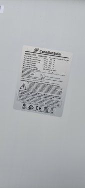
My bad on that. I used the operating voltage above. Yes, use the VOC or 45.5 x number of panels in a series. The only way you would see that would be if you put all 12 panels in a single series. In that case you would exceed the voltage at 546v. So you're going to need to split those into two strings of 6 (or some other configuration to stay under 500v). From there you could combine the two strings of 6 panels in parallel to give you a single string with 273v and 18.68a (9.34 isc x 2). If you exceed the amp rating the inverter will clip it but you don't want to exceed the max voltage. I think my math is right on this. Maybe someone else can chime in and confirm.Yes, sbu with no utility to either inverter. 1st 6500 has 3k on pv1 one 3.4k on pv2. On reaching the max 500 volts on the pv inputs, am I looking at open circuit voltage (49.5) x 12 or optimum operating voltage (37) x 12?
Madco
Solar Enthusiast
You need to take temperature into account if you are going to run close to the 500Vdc input maximum on the 6500. Your panel data doesn't include the voltage temperature coefficient, so use NEC table 690.7(A) along with the record low temperature for your area. For instance, if the lowest temperature is -10F, then the Voc rating of the panel needs to be multiplied by 1.2 (so 45.5 * 1.2 = 54.6V). The 500V limit allows you to go with a maximum of 9 panels in series. The inverter has a maximum MPPT voltage of 450V, so if you want to rule out the MPPT not running in an optimized fashion when it is really cold outside, then limit each input to 450/54.6 = 8 panels in series.
If it gets really cold in your area, failing to take the temperature coefficient into account can easily blow up the PV input on the unit.
If it gets really cold in your area, failing to take the temperature coefficient into account can easily blow up the PV input on the unit.
Madco
Solar Enthusiast
There's a little give and take on the MPPT calculations above. The open circuit voltage will drop rapidly as soon as the inverter pulls current from the panels. I was just trying to avoid the situation where it is very cold overnight, the sun comes up, and the inverter starts to pull power from the panels. In this case the MPPT may not start properly because the open circuit viltage is too high (above 450V).
I have a couple 6500s and the MPPT circuit acts flakey on occasion-not because of high input voltage but some other oddity. I'm just suggesting you rule out as many potential problems as possible!
I have a couple 6500s and the MPPT circuit acts flakey on occasion-not because of high input voltage but some other oddity. I'm just suggesting you rule out as many potential problems as possible!
Madco
Solar Enthusiast
no fuse is required with the two parallel strings and #10 wire. roof mounted panels opens up a bunch of cans of worms though. will these be ground mounted?
EastTexCowboy
Solar Wizard
Fuse? No. Breaker - yes I recommend a breaker between each PV string and the inverter. Make sure it is DC rated appropriately for your voltage and amperage. I also installed an exterior disconnect for the panels.I will probably go 6 in series into pv1 and 6 into pv2.... if later I decide to parallel the 2 strings with a y branch into pv1 do I need any type of fuse when using 10 gauge solar wire?
EastTexCowboy
Solar Wizard
It depends on the voltage and amperage on the PV circuits. I have four strings with a 63a 500v DC breaker on each. These are DIN rail mount breakers housed in an enclosed plastic box with the DIN rail. Here's the type of box I use but there are a lot of options on the box as well as the breakers. Just make sure they are DC rated.Ground mount. All my solar currently goes from solar panel to 10 gauge wire to a DC disconnect to pv imput. What breaker should I be using?
Similar threads
- Replies
- 12
- Views
- 581
- Replies
- 3
- Views
- 332
- Replies
- 3
- Views
- 225