• Have you tried out dark mode?! Scroll to the bottom of any page to find a sun or moon icon to turn dark mode on or off!

diy solar

diy solar

EG4 Chargeverter Battery/Inverter Communications

You had current and voltage reported wrong. "90 amps (VOLTAGE) at 54 volts (CURRENT)" should read "54 volts (VOLTAGE) at 90 amps (CURRENT)"

You were reporting the inverter's battery voltage readings, not the inverter's battery SOC readings, which led me to believe that you were in open-loop (voltage reading) 'communications' between the inverter and the batteries.

If your inverter is in closed-loop communications with the batteries, I wouldn't (in fact I don't) worry about what the voltages are. Use the SOC numbers from the inverter, the inverter will talk to the batteries and determine what they need for a voltage and charge them to whatever voltage makes the batteries happy (this will change as charging progresses).

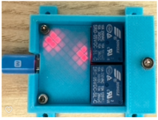
If the CV is charging the batteries based on voltage it may do something different, so you'll probably want to keep the CV voltage at 55.0V or something so as not to overcharge the batteries. I keep mine at 52V, which is sufficient to prop up the SOC to about 25% even though the CVs read 0.2 volts apart, and contribute different currents to the battery bank. I'm away for hurricane season now, so I can't make any changes, but when I get back I'll probably set the CV voltages to 55.0V and use the Gen Dry Contacts to enable the relays that power the CV AC inputs. Then I can set the 'generator' to come on at 20% and 'stop' at 40% or something. I'm working on a better control algorithm that'll probably run on the Raspberry Pi that's inside the primary inverter, so I can control charging based on weather (fully charge before hurricanes arrive, don't use grid power to charge the batteries if it's only a short time till sunrise, etc. But that's an optimization for later...
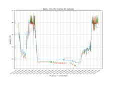
For instance, my batteries were full at 11:25AM, and the voltages, as reported by the inverters (Red and Green) and batteries (Blue and Cyan), wander all over the place. But again, voltage is a _really_ bad way to tell SOC from LFP batteries, so I don't worry about it, I figure the batteries are full and balancing themselves, so fully charged is fully charged, and I'm good. Once I get the CVs under control I'll probably set them for 55V so they won't overcharge the batteries, and let the inverter take care of the 100%SOC/balancing regime.
1720805357537.png
 
I read in the manual that there has to be a 5 volt difference between battery start and battery stop. I have mine at 5.2 volts difference and it still maintains a 90% charge. i will be making a relay soon between grid source and grid plug.
This is valid point, I only have 2 volt difference in my setup right now. It seems to not impact the Chargeverter though in my last two charging sessions which is odd. Shouldn't it not charge if it was adhering to the config settings of 54 volts BATT START 56 volts BATT STOP? I would think my last charging session started with my batteries well below 54 volts. It seems to me that without the communication cable or a two wire start generator connected to the CV, that the VC is ignoring the BATT START / BATT STOP settings, that's unless I'm overriding it somehow and don't know it.

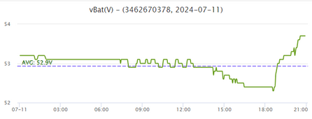
Here's the Battery Voltage graph from yesterday, you can see the voltage was a little over 52 volts when I started. I charged up until I went to bed so the CV didn't have a chance to stop itself at 56 volts.

1720807171540.png
 
I have written software that emulates an EG4 Lifepower4 battery. The communications are "EG4" which is in a HexAscii format. I do expect the CVGC it is acting as a "Master" which is why you can't have an inverter and the CVGC communicating with the batteries are the same time.

I will simply connect the CVGC to my computer where I can change SOC and battery voltages being reported to the CVGC to hopefully see how the CVGC controls charging based on the software settings. I also hope I can figure out if the CVGC settings can also be changed by software

I am also building a software "Master BMS" which does allow me to merge both EG4 LifePower4 batteries and SunGoldPower batteries. The inverter thinks it's communicating with a Master BMS when in fact it's communicating with my software. The software takes the data from all the batteries and properly reports (in response to inverter commands) data back to the inverter, for example an average of all battery SOC's and total amp hour capacity of all batteries in the bank.
Really looking forward to your software, assuming you are going to make it available? At this point, all the 18Kpv can tell me about the batteries is a single SOC number, a single voltage, a BMS current that makes no sense, and the max/min cell voltage across all 6 of my batteries, which is a 250mv span, but it's impossible to tell how the cells within a particular battery are balanced.

I keep holding out hope that using a special cable you could talk RS-485 to the batteries from the CVGC and CAN from the 18Kpv, but I can't even find anyone at SS/EG4 who knows what I'm asking, so maybe I'll have to try it when I can take my system down and try it myself...
 
This is valid point, I only have 2 volt difference in my setup right now. It seems to not impact the Chargeverter though in my last two charging sessions which is odd. Shouldn't it not charge if it was adhering to the config settings of 54 volts BATT START 56 volts BATT STOP? I would think my last charging session started with my batteries well below 54 volts. It seems to me that without the communication cable or a two wire start generator connected to the CV, that the VC is ignoring the BATT START / BATT STOP settings, that's unless I'm overriding it somehow and don't know it.

Here's the Battery Voltage graph from yesterday, you can see the voltage was a little over 52 volts when I started. I charged up until I went to bed so the CV didn't have a chance to stop itself at 56 volts.

View attachment 228246
Where are you reading "vBat(V)" from?
 
You had current and voltage reported wrong. "90 amps (VOLTAGE) at 54 volts (CURRENT)" should read "54 volts (VOLTAGE) at 90 amps (CURRENT)"
Good catch, I thought you were refering to the BATT START / BATT STOP settings. I've corrected this to avoid confusion for others in my first post.

You were reporting the inverter's battery voltage readings, not the inverter's battery SOC readings, which led me to believe that you were in open-loop (voltage reading) 'communications' between the inverter and the batteries.
Gotcha! Yeah, the EG4 18k has both readings when using closed loop comms if I'm understanding correctly.

1720819176162.png

If your inverter is in closed-loop communications with the batteries, I wouldn't (in fact I don't) worry about what the voltages are. Use the SOC numbers from the inverter, the inverter will talk to the batteries and determine what they need for a voltage and charge them to whatever voltage makes the batteries happy (this will change as charging progresses).
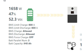
Agreed, but in this case the inverter isn't doing any charging. The CV is connected directly to the batteries and I don't currently have grid/solar providing any other power source. Unless I'm mistaken, the inverter is in the dark about the CV and what it's doing to the batteries, so I'm looking to regulate the batteries based on voltage by reading the average battery voltage reported on the inverter.

If the CV is charging the batteries based on voltage it may do something different, so you'll probably want to keep the CV voltage at 55.0V or something so as not to overcharge the batteries. I keep mine at 52V, which is sufficient to prop up the SOC to about 25% even though the CVs read 0.2 volts apart, and contribute different currents to the battery bank. I'm away for hurricane season now, so I can't make any changes, but when I get back I'll probably set the CV voltages to 55.0V and use the Gen Dry Contacts to enable the relays that power the CV AC inputs. Then I can set the 'generator' to come on at 20% and 'stop' at 40% or something. I'm working on a better control algorithm that'll probably run on the Raspberry Pi that's inside the primary inverter, so I can control charging based on weather (fully charge before hurricanes arrive, don't use grid power to charge the batteries if it's only a short time till sunrise, etc. But that's an optimization for later...
What you're saying makes sense I think, in my scenario I'm trying to get the CV to charge the batteries from 20-30% back to 80-90% as I don't have any other charging source. Hope this makes sense.
 
Last edited:
in my scenario I'm trying to get the CV to charge the batteries from 20-30% back to 80-90% as I don't have any other charging source.
And you are charging from a generator so you can’t just leave it running to balance? I’d (also I did) use the inverter’s Gen dry contacts to enable the power to the CV but you could always put the CVGC in closed loop mode and leave the inverter in open-loop mode till you get panels.
 
And you are charging from a generator so you can’t just leave it running to balance? I’d (also I did) use the inverter’s Gen dry contacts to enable the power to the CV but you could always put the CVGC in closed loop mode and leave the inverter in open-loop mode till you get panels.
Yes, I can leave it running to balance assuming the CV does shutoff at the BATT STOP setting. In my testing so far, it just wasn't clear if this was happening b/c I saw the battery voltage over 56 volts when I was charging last time with my setup and the CV set with a BATT STOP of 56 volts. I charged to 100% on the batteries and the CV did ramp down, but I wasn't sure if it was the CV causing this or the battery BMS stopping any further charging.

In theory the CV should slowly ramp down as it approaches the BATT STOP setting correct?

This is my big question. Seems like most are discussing the CV as if it does, but in practice and in the manual, I don't see this as happening for certain.

1720881074024.png
I can do some specific testing I suppose to find out for certain by setting the BATT STOP to something like 55 volts, then let the generator charge to that via the CV and see if the CV ramps down as most seem to predict.

I wish my generator had dry contacts, can't find a portable generator that has that feature.
 
Will you let us know if the CVGC does ignore the user start stop configs when plugged into grid power?
I've had it working for 2 days now. Confirmed the BATT START|STOP settings are ignored on shore power. However, it is working as desired as the VOLTAGE setting is obeyed instead. So I set that to the float voltage of 54.2v. Now it charges to 54.2 (99%) and stays there and the CV current goes to near 0. What is interesting is the demand current by the UPS is actually being supplied mostly by the CV and the CV current will go up with demand even though the batteries are charged. My guess is as amps are being pulled, for ex. by the HVAC, the battery voltage may drop so the CV starts to kick in again. Since the CV has a slow ramp-up it's not immediate, the power will come from the batteries first then the CV will compensate and recharge that.

I have to say it works like a charm. I can set a max current on the shore power (amps setting in the CV) so it draws for example 25A max on a 30A shore hookup. I won't have to pay the up-charge for the 50A service. The batteries mean I can run pretty much every appliance, 2 HVAC, coffee maker and convection oven and not trip a breaker. Also many campgrounds have crappy power that can kill appliances so the CV works like a power filter. Sweet!

Only downside...the CV is loud when supplying power! It's currently in my bedroom, I definitely have to move that...plus the 6000XP though it's not as bad.
 
Last edited:
You had current and voltage reported wrong. "90 amps (VOLTAGE) at 54 volts (CURRENT)" should read "54 volts (VOLTAGE) at 90 amps (CURRENT)"

You were reporting the inverter's battery voltage readings, not the inverter's battery SOC readings, which led me to believe that you were in open-loop (voltage reading) 'communications' between the inverter and the batteries.

If your inverter is in closed-loop communications with the batteries, I wouldn't (in fact I don't) worry about what the voltages are. Use the SOC numbers from the inverter, the inverter will talk to the batteries and determine what they need for a voltage and charge them to whatever voltage makes the batteries happy (this will change as charging progresses).

If the CV is charging the batteries based on voltage it may do something different, so you'll probably want to keep the CV voltage at 55.0V or something so as not to overcharge the batteries. I keep mine at 52V, which is sufficient to prop up the SOC to about 25% even though the CVs read 0.2 volts apart, and contribute different currents to the battery bank. I'm away for hurricane season now, so I can't make any changes, but when I get back I'll probably set the CV voltages to 55.0V and use the Gen Dry Contacts to enable the relays that power the CV AC inputs. Then I can set the 'generator' to come on at 20% and 'stop' at 40% or something. I'm working on a better control algorithm that'll probably run on the Raspberry Pi that's inside the primary inverter, so I can control charging based on weather (fully charge before hurricanes arrive, don't use grid power to charge the batteries if it's only a short time till sunrise, etc. But that's an optimization for later...
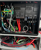
I would suggest putting the Raspberry Pi outside the primary inverter case, kind of like where the wifi adapter is. You can double-sided tape it to the side for example and bring in only the cable. Keep low voltage devices like RPis away from high-voltage...or in other words...keep your Pi out of the oven.
 
I would suggest putting the Raspberry Pi outside the primary inverter case, kind of like where the wifi adapter is. You can double-sided tape it to the side for example and bring in only the cable. Keep low voltage devices like RPis away from high-voltage...or in other words...keep your Pi out of the oven.
The environment inside the case is actually better for the Pi, it's hot, humid, and dusty outside, and it's far enough from the AC and battery connections that there's no concerns about it getting zapped. I mean, there's low voltage and RS485 and stuff in the same space...
Screenshot 2024-07-13 at 9.20.41 PM.png
 
The environment inside the case is actually better for the Pi, it's hot, humid, and dusty outside, and it's far enough from the AC and battery connections that there's no concerns about it getting zapped. I mean, there's low voltage and RS485 and stuff in the same space...
The placement of the LV you are talking about may be why the manual has strict rules on orientation of the 6000XP. If any of your HV cables come loose it could fall down and hit that RPi. Maybe it's not likely but it still happens so you could buy a cheap plastic cover to protect it...or print one since I see you can. :)

"The majority of the national electrical code was written in blood."
Yes, I will have to dig up the cover for the Pi, though the rapid shutdown will remove any power from wires that randomly fall off.
 
WPNS & GURU_Florida - Hi,
Been reading all this behind me with the EG4 CV.. I need a little help, maybe you can give me some feedback and your ideas.. If you don't mind.. taking the time.. Let me give you my setup and config.. I will try to keep this brief, as I can get a little long winded.
A. I am totally off grid, as there is no grid where I live.
B. Equipment - 8 PV 460w array on a two axis sun tracking..
4min / 12hr lapse/30% more production of PV
C. 3 - 150a LifePo4-50v in Parallel each Bat is BMS #1Pac is Master Pac #2+3 are daisy chained to Pac 1..RS485 Comm config
D. Growatt SPF6000t- DVM Split Phase 120/240 with latest firmware, Prog 05 - US2 Lithium bats, no BMS Comm
E. Generator 10kva 8k cont 30amp 240/60hz diesel currently connected to the Growatt AiO
F. Solar Assistant Orange PI- Growatt connected to SAPI & Batteries BMS connected to SAPI
G. EG4 Chargeverter on order inbound, be 4 weeks before it reachs me and I may have made a mistake in buying it pending what DIY info
Here's the Plan - Once the EG4 CV arrives, I disconnect my Gen from the Growatt , connect to the EG4 CV, I plan on RS485 from the Bat BMS CAN port, not the RS485 port directly to the EG4 CV, which may or may not communicate

But here is my Real Concern. I have been hearing that I am not to be charging batteries, while the Growatt is pulling from the batteries or charging the batteries.. The issue is this.. with this Growatt, it has to have the batteries powering it.. secondly, it pulls from the batteries and pushes to the batteries, 24/7 pending the Sun PV being generated.. and the house load.. I was told to not have the AiO on while charging, which make no sense and defeats having an AiO and being Off Grid..

What I don't know and don't want to risk a $2k AiO over a $400 EG4 CV, in order to charge.. my gen is not inpulse wish it was. its dirty power and concerned if I keep using it will damage some house equipmt, fortunatley not often, say a few hours one or two times a month.. as my average SOC runs to 99% day to next morning 75-80% SOC to start all over.. now there are times like the past three days, running 70% days to pm, and by am is 50-55%..little to no sun

Any ideas on how much risk I have with the Growatt /EG4 CV being connected at the battery Bus jointly that the two get in a pissing match and I know who will blow up (Growatt). In three years I have learned that the Growatt is so sensitive that if you look at it the wrong way it will tell you about it.. lol Thanks for your input in advance, if any.. Regards - Ric

Ps. somewhere I heard or read that your not suppose to do Charging with EG4 and AiO pulling loads, I contacted EG4 with this and they came back with wanting to know if I had a silver lable on the battery and update, not sure where they got that idea, as I mentioned I am using 3rd party LifePo, replied back and they never replied back again.. I askaed the people where I purchased at SS.. and they came back said might be ok, but to be on the safe side, don't have the AiO pulling loads when charging. which makes no sense, seems defeats the whole concepts.. Now, in the EG4 CV manual, I can't find a word about what I am asking.. only No closed Loop on BMS with Inverter and BMS with EG CV. Use Start Stop Voltage, since it has to have BMS to use SOC. sorry long winded.
 
Last edited:
Not a concern to charge the batteries in open loop (voltage mode) while using them (closed loop) with the inverter.

While conceptually the inverter can tell there’s something squirrelly going on (inverter net (dis)charge current and BMS current sums don’t add up, no inverter in the known universe checks this or throws an error. It just looks to the inverter like the batteries don’t discharge as fast as they ‘should’.

Set the ChargeVerter to 55 or 56 volts and charge manually when required.
 
The CVGC will always charge when there is an AC (grid or generator) input and the CVGC Charge Voltage is greater than the battery voltage as measured at the CVGC output. If there is AC input and the inverter is running then the CVGC will provide output that will be used by the inverter or for charging the batteries depending on battery voltage and/or inverter load.

The only way to turn off the CVGC and stop it's charging is to remove the AC input (disconnect grid via contactor/relay or shut down the generator). The CVGC internal electronics however are powered by some internal power derived from the battery connection or the AC input. Disconnect AC and open the breaker and the CVGC will power down. This means that as long as the CVGC breaker is closed the CVGC is also an idle/parasitic load on the batteries (albeit small) just like the inverter's idle draw.

The "SOC START", "SOC STOP", "BAT START" and "BAT STOP" setpoints only control operation of the "Dry Contacts" which in turn can be used to control the AC input, either controlling a contactor/relay or controlling the start/stop of a generator. The "Dry Contacts" of the CVGC could also be paralleled (I would use diode isolation) with the appropriate "Dry Contacts" of the inverter and in some cases the "Dry Contacts" of one or more batteries.

The Voltage as displayed on the main screen is either the voltage measured at the CVGC output terminals with no BMS input or the voltage reported by the BMS with BMS input. The Current is the current as measured by the CVGC output. the SOC is "LOST" with no BMS input or the BMS reported SOC with BMS input.

The CVGC sends a modbus command 01-03-00-13-00-11-74-03 to the "Master BMS" (every 1 second). 00-13 is register 19 and 00-11 requests 17 sequential register values. 74-03 is the CRC of the command. For the BMS communications to work there must be a "Master BMS" which is a battery with address 0 (all dip switches down). The "Master BMS" returns: "01-03-22-04-65-00-00-00-63-14-FE-00-00-00-1B-75-30-E8-08-EA-60-01-01-00-00-00-00-00-00-00-64-16-80-00-00-00-00-D5-B1" (without dashes):

Register Hex Register Raw Value Calc Value Register Name
19 0x13 1125 1125 Not Defined
20 0x14 0 0 Not Defined
21 0x15 99 99 Battery SOC (%) change this changes the displayed CVGC value
22 0x16 5372 53.72 Battery Voltage (VDC) change this changes the displayed CVGC value
23 0x17 0 0.00 Battery Current (AMPS)
24 0x18 27 27 Not Defined
25 0x19 30000 300.00 Bank Max Charge Amps (AMPS) *
26 0x1A 59400 594.00 Bank Remaining Capacity (%) *
27 0x1B 60000 600.00 Bank Total Capacity (AH) *
28 0x1C 257 257 Not Defined
29 0x1D 0 0 Not Defined
30 0x1E 0 0 Not Defined
31 0x1F 0 0 Not Defined
32 0x20 100 100 Max Charge Amps (AMPS)
33 0x21 5760 57.60 Max Charge Voltage (VDC)
34 0x22 0 0 Not Defined
35 0x23 0 0 Not Defined

With the exception of the two I change when I intercept the data before it is sent to the CVGC, the other values are guesses as to what they are. The three with the * will vary depending on the number of batteries connected via cat5 to the "Master BMS". For example the "Bank Total Capacity (AH)" is 100.00 with only the Master battery and increases by 100 for each additional battery connected via the cat5/ethernet cable

I did receive an RS485 to USB cable with my CVGC. I can only assume that it would be used for future firmware updates as it has no use in a normal installation.

I have tried a number of different scenarios with CVGC communications (including testing pins 7&8 of the RJ45 jack) to determine if the CVGC settings could be read and/or set with software. So far, no luck but will continue to try.
 
Not a concern to charge the batteries in open loop (voltage mode) while using them (closed loop) with the inverter.

While conceptually the inverter can tell there’s something squirrelly going on (inverter net (dis)charge current and BMS current sums don’t add up, no inverter in the known universe checks this or throws an error. It just looks to the inverter like the batteries don’t discharge as fast as they ‘should’.

Set the ChargeVerter to 55 or 56 volts and charge manually when required.
WPNS, thanks for your reply. Appreciated.. and Duly noted.. just for clarity, I do not have my Battery BMS connected to the Growatt. Only to the Solar Assistant Orange PI, not sure if that makes any difference.. I can say since I just started in May using the SA PI, and with the Growatt and BMS connected to the Orange PI my overall health of Charging and Batteries, etc as well the Growatt SPF has improved.. I don't think the Growatt sees or directly communicates with the BMS batteries.. since I have Growatt Program 05 - selected as US2 which is No BMS communicatons but has Lithium batteries to work with..

My understanding is far less on the whole ops, guess maybe enough to be dangerous to myself, lol However if my recall is correct.. the Battery BMS connected to the EG4 Port BMS comm is mostly for the Dry contact SOC & Gen/AC Grid as to know when to charge batts or stop , by opening the circuit to and from the Gen/AC Grid using the SOC from Bat BMS

Thus, if I understand your suggestion, A. do not connect Bat BMS to EG4CV, in that case the CV just uses the Bat Volts settings as to know
when in my case the Gen is powering the CV, and CV then according to Volt settings will charge my Bats..

My concern overall is I am being told that I should Not use the EG4CV to charge with any heavy loads on the AiO only no loads or light loads,, which I am now wondering if I should have just invested in Inverter Generator.. For me there is no such " No Loads" as being Off Grid, home is only powered by the Growatt. As for light loads, not sure what parameter is meant. by evening, say 6pm to 9pm, I'm pulling 10 amps, after 9am the demand on the Growatt falls back to 5-6amps until 6am, when we awake. I did not want to be running Generator at 9pm - mostly Noise for me and surrounding homes even thou they are not that close..

Please correct my following theory - Scenerio
a. daytime/nighttime, little to no sun.all day, from 7am to 5 pm.. batteries are rdischarging at 5-9 amps/hr by 4 pm SOC are at 50% even though the PV array is producing 3-5 amps, and I want to use the EG4 to charge and top up Bats.. so I fire up the Gen, plug in the EG4 and set to 60A.. since the Growatt is still pulling from the batteries all day, because the watts demand is greater than the PV watts input Growatt provides power using both the batteries and the PV array. I am just concerned how the Growatt will see the added Amps coming from in. From Something since it has no idea there is the EG4.

Normally the way the Growatt is setup, the Gen is connected to the Growatt, which allows up to 60A input from the Gen. but my gen can only do 30a.

b. Why can't I just connect the EG4 to the Growatt, which for my model allows 60A max from Gen.. only issue is when you use the Gen to the Growatt.. the Growatt takes Gen power to feed the house and if the demand is more than the Gen the it will pull from the Bats as well, say there is a 20am pull from the house, the other 40 amps would go to batteries, and if there is PV amps available, it will apply up to another 60 amp on top of the 40.. as the limit total to the batteries at any one time from whatever is 100amps. In this scenario.. my concern then is the EG4, I don't think it was designed for this type hook up.. it was in my understanding to connect the EG4 directly to the battery bus not the AiO Grid/Gen Bus.
Could you set me straight on my thinking above.. Appreciate Thanks Ric Oops , I m have asleep,, I just remember, the EG4 is DC Amps to Battery Bus, not AC to the Growatt.. forget the above suggestion about connecting to the AC Grid terminals of the Growatt. that would really cause some smoke. lol
 
Last edited:
WPNS, thanks for your reply. Appreciated.. and Duly noted.. just for clarity, I do not have my Battery BMS connected to the Growatt. Only to the Solar Assistant Orange PI, not sure if that makes any difference.. I can say since I just started in May using the SA PI, and with the Growatt and BMS connected to the Orange PI my overall health of Charging and Batteries, etc as well the Growatt SPF has improved.. I don't think the Growatt sees or directly communicates with the BMS batteries.. since I have Growatt Program 05 - selected as US2 which is No BMS communicatons but has Lithium batteries to work with..

My understanding is far less on the whole ops, guess maybe enough to be dangerous to myself, lol However if my recall is correct.. the Battery BMS connected to the EG4 Port BMS comm is mostly for the Dry contact SOC & Gen/AC Grid as to know when to charge batts or stop , by opening the circuit to and from the Gen/AC Grid using the SOC from Bat BMS

Thus, if I understand your suggestion, A. do not connect Bat BMS to EG4CV, in that case the CV just uses the Bat Volts settings as to know
when in my case the Gen is powering the CV, and CV then according to Volt settings will charge my Bats..

My concern overall is I am being told that I should Not use the EG4CV to charge with any heavy loads on the AiO only no loads or light loads,, which I am now wondering if I should have just invested in Inverter Generator.. For me there is no such " No Loads" as being Off Grid, home is only powered by the Growatt. As for light loads, not sure what parameter is meant. by evening, say 6pm to 9pm, I'm pulling 10 amps, after 9am the demand on the Growatt falls back to 5-6amps until 6am, when we awake. I did not want to be running Generator at 9pm - mostly Noise for me and surrounding homes even thou they are not that close..

Please correct my following theory - Scenerio
a. daytime/nighttime, little to no sun.all day, from 7am to 5 pm.. batteries are rdischarging at 5-9 amps/hr by 4 pm SOC are at 50% even though the PV array is producing 3-5 amps, and I want to use the EG4 to charge and top up Bats.. so I fire up the Gen, plug in the EG4 and set to 60A.. since the Growatt is still pulling from the batteries all day, because the watts demand is greater than the PV watts input Growatt provides power using both the batteries and the PV array. I am just concerned how the Growatt will see the added Amps coming from in. From Something since it has no idea there is the EG4.

Normally the way the Growatt is setup, the Gen is connected to the Growatt, which allows up to 60A input from the Gen. but my gen can only do 30a.

b. Why can't I just connect the EG4 to the Growatt, which for my model allows 60A max from Gen.. only issue is when you use the Gen to the Growatt.. the Growatt takes Gen power to feed the house and if the demand is more than the Gen the it will pull from the Bats as well, say there is a 20am pull from the house, the other 40 amps would go to batteries, and if there is PV amps available, it will apply up to another 60 amp on top of the 40.. as the limit total to the batteries at any one time from whatever is 100amps. In this scenario.. my concern then is the EG4, I don't think it was designed for this type hook up.. it was in my understanding to connect the EG4 directly to the battery bus not the AiO Grid/Gen Bus.
Could you set me straight on my thinking above.. Appreciate Thanks Ric Oops , I m have asleep,, I just remember, the EG4 is DC Amps to Battery Bus, not AC to the Growatt.. forget the above suggestion about connecting to the AC Grid terminals of the Growatt. that would really cause some smoke. lol
Again, you are getting yourself all twisted up over how this won't work. Here's how it will work:

Connect the ChargeVerter AC Input to the generator
Connect the ChargeVerter DC output to the batteries.
Set the ChargeVerter to something like 55 or 56 volts. Whatever your batteries want, I can't tell from here.
Start the generator and then turn on the ChargeVerter DC breaker.
Run the generator till the battery charge reaches your desired SOC. I wouldn't go all the way to 100% as this may take a long time. Stop at 90% or something to save generator runtime.

Turn off the ChargeVerter DC breaker, shut down the generator, and you're done.

Now, once you have that working, if you want to automate things, come back and ask those questions. #OneStepAtATime
Yes, thanks I understand all that you have guided.. battery max limits by mfg. is 53v.. I plan on setting the CV to 60a and Stop charge at 51v and Start charge at 48v my batteries never fall below 48.6 v and never seen them go above 50.1 during charge SOC 99%
I will come back after receiving and hooking up.as to report and get your input.. In meantime Thank You - Regards - Ric - it will be 4-6 weeks before this happens because that is the shipping time from USA to my location in the South Pacific, I think they have to find a plane and pilot to get it here.. lol, then three government entities have to do inspections on shipment and VAT fees. 4-6 weeks enroute time.
 
Hi all. I hooked up my chargeverter (2nd gen - black case) to 120V today, as I'm waiting on a new inlet box and just did a temporary cord. There is no AC (grid or gen) connected to the inverters, and we are running on battery only (panels also not yet hooked up). Batteries are set to communicate with the inverter, so no comms (thus no SOC) available to the CV. Batteries/inverter are showing batteries at 52.4 volts (38% SOC) while CV is showing 53.0V. I can't get the Batt Stop Volts on the CV to go over 57 in the settings (makes sense), so I just backed that down to 56.8 as apparently recommended to an earlier poster by Current Connected. I then set the Batt Start Volts to 51.8 to get the necessary 5V spread between those two parameters. Given that the chargeverter never started charging while I was doing all this, I'm ASSUMING that I need to see Batt voltage drop to 51.8 as measured by the CV for it to start charging, and that it will then continue charging until it hits 56.8, given my settings.

Is that right?

If so, I guess the batteries will need to drop down to about 33-36% SOC (maybe a bit less as measured by the BMS) before the CV kicks on. Will report back once we drop some more battery power, but any input welcome prior to that.
Why do the start/stop thing to prove function? Just set the voltage to 55V, the current to 100A, and power it up. Note that it'll take a few minutes to start ramping up and will ramp up very slowly, so you may not think it's doing anything...
 
Why do the start/stop thing to prove function? Just set the voltage to 55V, the current to 100A, and power it up. Note that it'll take a few minutes to start ramping up and will ramp up very slowly, so you may not think it's doing anything...
Screenshot 2024-07-29 at 7.57.43 PM.png
This worked just fine for testing function.
 

diy solar

diy solar
Back
Top