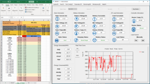
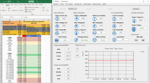
I had a hot, sunny morning and into mid-afternoon. I boost charged at 45-50 amps from 11a to about 2P, then switched to float. Around 2:30p, some clouds rolled through, creating a variable input while in float. It took about 20 minutes of high variability to hit boost recon. Once in boost, it only took about 15 minutes to get back to float. This happened a second time from passing clouds, as opposed to heavier variable load. When the suns is constant, I can't load it enough to drop back into boost. The float rises to meet any load I demand.
The controller dropped into float slightly below the set boost voltage and ran in float with a fair variability, mostly between boost and boost recon voltages, never above boost, but sometimes below boost recon. I may tighten the boost to boost recon voltage a bit and see if that gets less variable. The boost recon kicked in after the system spent 5-10 minutes below the set boost recon voltage so not as quickly as i expected, but tolerable.
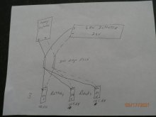
My load is approximately 16KW/day, split into two pieces, constant (about 13KW) and intermittent (about 3KW). The constant load runs about 550 watts, 24 hours a day. The surge is from the refrigerator which uses about 1,100 watts to start, then runs about 120 watts. The coffee pot uses about 1,000 watts and cycles around 50% while in use. I have two 24v inverters, one 500w and one 1,500w. The 500w runs my WISP equipment, LED light strings in the whole house and a box fan. The 1,500w runs my kitchen and my main working desk system (4 laptops, 4 32" monitors, 6 iphones, two raspberry pi's and two usb desk fans) and another box fan. I am using my old sealed lead acid cells as 24v buffers for the inverters. The 500w has 24v, 150a lead acid battery bank and the 1500w inverter has 24v, 220a lead acid battery bank directly attached. I use a 48v-24v buck converter to supply a steady charge to the subsystem, set to a couple amps above the constant load. All the surge loads draw down the lead acid, while the constant loads are fed from the main bank. When a surge draws down the subsystem, the charge from the main system rises to restore it to a preset voltage. This works FANTASTIC, allowing me to surge the 24v inverters to max+ load without passing the surge to the main bank. The limiting in the buck converter allows me to have a max draw on the circuit until the 24v battery gets back to optimal voltage, then taper back to the constant load.
I have a 48v, 3,000w inverter coming Monday so that will require a re-think on the design.