diy solar

diy solar

EVE 280ah 16S battery build process?

Brandan

New Member
Joined
Jan 6, 2023
Messages
15
Location
England
Hey guys!

Been looking around for what i need to build myself a LFP battery for my Growatt SPH 6000 and have done endless research on everything. I have found where i want to buy my battery cells from and know what BMS i will be using etc...

I have been compiling what i need to do and in what order but come across alot of conflicting info on if i should top/bottom balance, to compress the cells or not and if i should put anything in-between the cells etc...

To get to the point I'd like to ask if anyone knows or has a guide of sorts that goes through all of this stuff start to finish as everything i find on YouTube is somewhat vague and doesn't go into as much detail as I'd have liked it to.

Any discussion or resources are welcome

Thanks guys ?
 
- Top balance, but be careful how. I just tend to put the cells together in a pack and let the active balancer take care of balancing over time. If you want to manually top balance, check this https://diysolarforum.com/ewr-carta/handbook/ and other resources on this website.

- I recommend a fixture for the cells, but people run them without. Compression is a bit of a misnomer. Don't apply a huge compression force. Again, search this site for ideas/opinions. Put some thin foam in between, or some fibrerglass board (like PCB material).

A lot of these issues are personal opinion, but there are some common best practices. You're not going to find a single guide, but all the info should be around here.
 
I'm in the same boat. I haven't decided on compression. If I don't compress, then I won't put anything in between because of strain on terminals.

I am looking into flexible bus-bar. Saw a discussion on amps, and you need at least 10mm thick busbar connecting the batteries if you want to discharge at 1c. Best I saw was 4mm flexible bus-bar.

Fortunately, it will be 1 of 3 banks, but just in case the other banks are down, I wanted to be able to pull 1c from it in an emergency.

If the solid bus bars are long enough that there is a gap between the batteries (helps to keep temp down?), then I won't worry about swelling putting strain in the battery.
10mm for 1C seems pretty thick to me.
 
Compression is a bit of a misnomer. Don't apply a huge compression force.
I guess I'll go ahead and disagree on this one. EVE does specify compression in their data sheet, and it is 300 kgf (~660 pounds) on the face of the cells. It seems like the question these days is whether hard compression (no foam or springs) is what the most recent data sheet really says. That certainly is the implication.
 
If I don't compress, then I won't put anything in between because of strain on terminals.
I'm in the 'compression/fixture isn't necessary' camp. But you should still consider putting some sort of insulating material between the cells. The blue shrink-wrap isn't just aesthetic, it's to prevent case-to-case shorts, and you may not want to rely on just the shrink-wrap. If the issue is that your bus bars aren't long enough to accommodate, you probably need longer bus bars.
Saw a discussion on amps, and you need at least 10mm thick busbar connecting the batteries if you want to discharge at 1c. Best I saw was 4mm flexible bus-bar.
This is definitely not true. You don't mention what your C-rate is, but the standard 2mm thick, 20mm wide bus bars should be good for over 200 Amps.
See this reference. 1/16" by 1" is the same cross-section as 2mm x 20mm.
Keep in mind that bus bars don't need nearly as large a cross section as insulated cable because: 1. They're short, so voltage drop over distance isn't much of an issue, and 2. They're uninsulated, so the heat they produce dissipates much better.
 
I guess I'll go ahead and disagree on this one. EVE does specify compression in their data sheet, and it is 300 kgf (~660 pounds) on the face of the cells. It seems like the question these days is whether hard compression (no foam or springs) is what the most recent data sheet really says. That certainly is the implication.

I agree, but that 300kgf is, if you take the common approach of two plates with four threaded rods, the nuts on those rods hand-tight. That's why I don't like the term compression since it might give people the idea they need to torque those nuts like crazy.
 
This is definitely not true. You don't mention what your C-rate is, but the standard 2mm thick, 20mm wide bus bars should be good for over 200 Amps.
See this reference. 1/16" by 1" is the same cross-section as 2mm x 20mm.
I mentioned a 1c rate that assumed the 280ah in the title of the thread, or 280 amps. The table you referenced implies 4.6 amps per sq mm. The "rule of thumb" I keep seeing is 1.2 (most) to 1.6 (few) amps per sq mm.

For the larger bar sizes it does seem to get closer to 1.2. maybe it is the larger percentage of surface area effect where most of the current is carried and heat is dissipated.
 
I agree, but that 300kgf is, if you take the common approach of two plates with four threaded rods, the nuts on those rods hand-tight. That's why I don't like the term compression since it might give people the idea they need to torque those nuts like crazy.
Trying to convert thread torque to compressive force is the fool's errand in that case. It is very hard to accurately deduce force from torque applied without actually measuring your setup first. Any lubrication or difference in polish on the threads will change the force given the same torque. When dealing with relatively small torque values, the ability to get what you expect can be difficult.

The formula is: T = K F d (1 - l/100),
where: T is torque;
K is friction coefficient;
F is force required;
d is fastener diameter;
I is lubrication factor

The friction coefficient "K" used for calculating the *estimated* force from torque can vary as much as 100%. For example, one might use the following for mild steel fasteners:
  • normal dry: K = 0.2
  • nonplated black finish: K = 0.3
  • zinc-plated: K = 0.2
  • slightly lubricated: K = 0.18
  • cadmium-plated: K = 0.16
 
I have been compiling what i need to do and in what order but come across alot of conflicting info on if i should top/bottom balance, to compress the cells or not and if i should put anything in-between the cells etc...

To get to the point I'd like to ask if anyone knows or has a guide of sorts that goes through all of this stuff start to finish as everything i find on YouTube is somewhat vague and doesn't go into as much detail as I'd have liked it to.
Here is the 48v LF280k Battery Build I am planning on:
  • 16 LF280k (nominal 3.2v each). Assumes the dual M6 terminals.
  • JK BMS 8-24S-200A continuous, 350A Peak, Active Balancing JK-B2A24S20P (B2A: 2A active balance, 24S: up to 24 batteries in series, 20P: 200A power continuous).
  • JK BMS Power Switch or Monitor with Switch
  • JK BMS-RS485 (if you want to monitor with Solar Assist)
BMS: Want Active Balance for cells that large.
  • Class T Fuse Holder
  • Class T Fuse (250 amps?)
  • Shunt
  • Optional: On/Off Switch (400A, 60V DC Rated)
  • Something to mount the BMS/Fuse/Shunt on
For the JK BMS:
2 M6 (1/4 inch) Ring Terminals (Main connection to Battery)
2 M10 (3/8 inch) Ring Terminals (to connect to Shunt)
18 M6 Ring Terminals (to connect all the small wires to each cell

For the Shunt:
1 2/0 Wire with M10 ring terminal on one end. Don’t know what the Growatt has.

For Optional On/Off Switch:
2 6 AWG wire with M6 ring terminal on one side, and M10 on the other (to connect to Battery).
1 2/0 Wire with M10 ring terminals on both end (to connect to Fuse Holder)

For Fuse Holder:
1 2/0 Wire with M10 ring terminal on one end. Don’t know what the Growatt has.

Fuse: The Blue Sea Class T fuse has a long delay near the rated amperage for blowing. At 110% of rating, it should be able to go 15-30 minutes before blowing. I may draw up to 275 Amps with my inverter, but that is only if other batteries drop out, and I am running everything. Otherwise, I anticipate drawing 90 amps (0.3 c) max, and more likely 30 amps (0.1 c) max sustained rate.

Optional:
  • Pre-charge resistor
  • Crimper for Ring Terminals (for the BMS).
  • For the larger wire, you would need a larger crimper, or buy pre-made wire.
  • Flexible Busbars (reduces strain on battery terminals from expansion/contraction of batteries)
  • Insulators (electrical) between batteries.
  • Power supply to charge/balance the batteries
  • Something to box/compress the batteries. Lots of conflicting advice regarding compression. It will be hard to measure compression force. But a rigid box may get close enough. 300kgf (661 lbf) is recommended for EVE LF280K. I found these springs on Amazon (one of the few with force/mm info): https://www.amazon.com/dp/B07GSNCYNK/

Assembly:

Battery - <> BMS <> Shunt <> Inverter
Battery + <> On/Off switch <> Fuse <> Inverter
  • Wire batteries in Series, and connect BMS.
  • Download JK BMS app, and connect to battery (DO NOT CHANGE PASSWORD – known problem with app).
  • Setup parameters for 16 battery full charge. Make sure it all seems about right (cell voltages, etc.)
  • Pre-Charge up to full (somewhere between 54.4v (3.40v per cell) to 58.40v (3.65v per cell)). I would do 57.6v. I have a Chargeverter, but could also use the Inverter. If you use the inverter, follow proper procedures to connect (pre-charge resistor).
  • Let battery charge until BMS does over-voltage disconnect.
  • Immediately after cutoff check individual cell voltages (if you wait, batteries will settle, and no longer be a good indicator). If within 50mv (0.050v high to low), then skip top balance. If 50-150mv, then your choice. If over 150, then need to top balance.
  • Top balance: Use BMS: Float at 54.4v until all the cells are balanced. Otherwise: Disconnect everything, and wire cells in parallel. Charge with powersupply at 3.50v to 3.60v. Follow top balance instructions for detailed instructions and cautions.
  • No need to bottom balance with BMS.
  • Reassemble (if necessary), and adjust BMS Settings for normal operation (high/low limits)
  • Connect to Inverter (follow instructions regarding pre-charge resistor).
  • If connecting with other batteries, charge all batteries to the same voltage before connecting together.
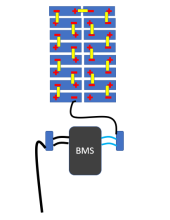
Wrt the connection of the bms to the negative pole of the battery, and the negative of the inverter, you might want to consider two busbars.

One thick wire from cell one to busbar, busbar to bms, bms to other busbar, busbar to inverter.

This will give you much more flexibility regarding installation. The wires on the bms are pretty short. Also no double connections under one nut.
 
I did it like this picture.
With regards to the wire thickness, I don't know how much amps you will draw from your battery, but it is my understanding that 2/0 is about 70mm2. Sounds enough to me.
1685021794870.png
 
Here is the 48v LF280k Battery Build I am planning on:
  • 16 LF280k (nominal 3.2v each). Assumes the dual M6 terminals.
  • JK BMS 8-24S-200A continuous, 350A Peak, Active Balancing JK-B2A24S20P (B2A: 2A active balance, 24S: up to 24 batteries in series, 20P: 200A power continuous).
  • JK BMS Power Switch or Monitor with Switch
  • JK BMS-RS485 (if you want to monitor with Solar Assist)
BMS: Want Active Balance for cells that large.
  • Class T Fuse Holder
  • Class T Fuse (250 amps?)
  • Shunt
  • Optional: On/Off Switch (400A, 60V DC Rated)
  • Something to mount the BMS/Fuse/Shunt on
For the JK BMS:
2 M6 (1/4 inch) Ring Terminals (Main connection to Battery)
2 M10 (3/8 inch) Ring Terminals (to connect to Shunt)
18 M6 Ring Terminals (to connect all the small wires to each cell

For the Shunt:
1 2/0 Wire with M10 ring terminal on one end. Don’t know what the Growatt has.

For Optional On/Off Switch:
2 6 AWG wire with M6 ring terminal on one side, and M10 on the other (to connect to Battery).
1 2/0 Wire with M10 ring terminals on both end (to connect to Fuse Holder)

For Fuse Holder:
1 2/0 Wire with M10 ring terminal on one end. Don’t know what the Growatt has.

Fuse: The Blue Sea Class T fuse has a long delay near the rated amperage for blowing. At 110% of rating, it should be able to go 15-30 minutes before blowing. I may draw up to 275 Amps with my inverter, but that is only if other batteries drop out, and I am running everything. Otherwise, I anticipate drawing 90 amps (0.3 c) max, and more likely 30 amps (0.1 c) max sustained rate.

Optional:
  • Pre-charge resistor
  • Crimper for Ring Terminals (for the BMS).
  • For the larger wire, you would need a larger crimper, or buy pre-made wire.
  • Flexible Busbars (reduces strain on battery terminals from expansion/contraction of batteries)
  • Insulators (electrical) between batteries.
  • Power supply to charge/balance the batteries
  • Something to box/compress the batteries. Lots of conflicting advice regarding compression. It will be hard to measure compression force. But a rigid box may get close enough. 300kgf (661 lbf) is recommended for EVE LF280K. I found these springs on Amazon (one of the few with force/mm info): https://www.amazon.com/dp/B07GSNCYNK/

Assembly:

Battery - <> BMS <> Shunt <> Inverter
Battery + <> On/Off switch <> Fuse <> Inverter
  • Wire batteries in Series, and connect BMS.
  • Download JK BMS app, and connect to battery (DO NOT CHANGE PASSWORD – known problem with app).
  • Setup parameters for 16 battery full charge. Make sure it all seems about right (cell voltages, etc.)
  • Pre-Charge up to full (somewhere between 54.4v (3.40v per cell) to 58.40v (3.65v per cell)). I would do 57.6v. I have a Chargeverter, but could also use the Inverter. If you use the inverter, follow proper procedures to connect (pre-charge resistor).
  • Let battery charge until BMS does over-voltage disconnect.
  • Immediately after cutoff check individual cell voltages (if you wait, batteries will settle, and no longer be a good indicator). If within 50mv (0.050v high to low), then skip top balance. If 50-150mv, then your choice. If over 150, then need to top balance.
  • Top balance: Use BMS: Float at 54.4v until all the cells are balanced. Otherwise: Disconnect everything, and wire cells in parallel. Charge with powersupply at 3.50v to 3.60v. Follow top balance instructions for detailed instructions and cautions.
  • No need to bottom balance with BMS.
  • Reassemble (if necessary), and adjust BMS Settings for normal operation (high/low limits)
  • Connect to Inverter (follow instructions regarding pre-charge resistor).
  • If connecting with other batteries, charge all batteries to the same voltage before connecting together.
This is the kinda detail I've been searching for, thanks!. Also i still have the issue with setting ovp and uvp as i dont know what to set them as, i want to only use the battery between 10% and 90% soc.

I have since first starting this thread found that the JK BMS i wanted to use may not work with a growatt inverter so im back to the drawing board in regards to a BMS lol
 
I agree, but that 300kgf is, if you take the common approach of two plates with four threaded rods, the nuts on those rods hand-tight. That's why I don't like the term compression since it might give people the idea they need to torque those nuts like crazy.
For my CATL cells I hand tightened the nuts on the rods holding them together and this has worked very nicely. The current case I received for my EVE cells has screws that can be tightened down. The current gentle hand tightening has worked well for my existing cells. Will likely use the same approach for this case.
 
Back
Top