alcoolaid
New Member
Update: With the help here and more discussion with the rep, we figured it out! Thanks for the help everyone!
Below is a snippet of my solar permit plan notes I submitted to GreenLancer.
Solaredge SE-10000H-US
Solaredge S440 Optimizers
34x 410w panels. 18 over the house (house array), 16 over the garage (garage array).
This is where I get very confused. Read from the bottom up. (Names have been partially redacted). Why the heck is he saying I need 8 awg cable? Is my description of how I want to do the system not clear? I'm ready to submit an email to ask for a refund so I can go with a local route. I had a friend who works for a local solar company read the information below and he doesn't understand it either?
String A: 8 panels x 410w = 3,280w / 400v = 8.2A
String B: 8 panels x 410w = 3,280w / 400v = 8.2A
String A + B combined in fused combiner box = 6,560w / 400v = 16.4A
Output is 10 awg wire to inverter
House Home Run 2
String C: 9 panels x 410w = 3,690w / 400v = 9.2A
String D: 9 panels x 410w = 3,690w / 400v = 9.2A
String C + D combined in fused combiner box = 7,380w / 400v = 18.45A
Output is 10 awg wire to inverter
Home run 1 and home run 2 meet at the inverter. Home run 1 and home run 2 will each carry a max of 16.4A and 18.45A respectively.
I'm not sure how you're getting 37.5A being carried on 10 awg wire? It's only 16.4A from the garage array and 18.45A from the house array? They both meet at the inverter junction block.
410w panels x 18 = 7.38 kw / 400v = 18.45 amps?
Or am I understanding something wrong.
Were you able to see this note as shown below?
Garage array:
Soladeck with fused combiner combining two strings of 8 panels. 10/2 FMC coming out from bottom of soladeck into attic space, come down wall of interior garage space (NW corner), enter PVC JB (covert to 10 awg THHN), go through PVC conduit underground to house basement. Inside basement will have PVC JB and convert back to 10/2 FMC to inverter. Might need a DC disconnect by garage? Not sure if that is necessary.
House array:
Soladeck with fused combiner combining two strings of 9 panels. 10 awg THHN in EMT across roof to edge and down along the side of the house. Enter house near meter and into inverter. Or can run two pairs of 12 awg wire and forego a combiner on the house roof (probably the cheaper option?).
To summarize:
Garage - 10 awg run for 16 panels (8 series, 2 parallel)
House - 10 awg run for 18 panels (9 series, 2 parallel)
Thanks,
Arthur
we need clarify with you cable size issue. We can connect into the inverter only three strings. According to your design PS system will have 4 PV strings. It's mean we should combine two strings into one before connection into the inverter. If we combine two string we will have max. current 37.5A. Base ampacity for 10 awg cable is 40A and terminal amp is 35A. So we can not use 10awg for string combining. For string combining more better use 8 awg.
Please inform us how we should proceed.
Thank you
Below is a snippet of my solar permit plan notes I submitted to GreenLancer.
Solaredge SE-10000H-US
Solaredge S440 Optimizers
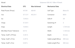
34x 410w panels. 18 over the house (house array), 16 over the garage (garage array).
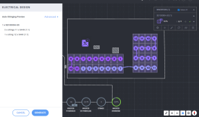
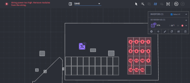
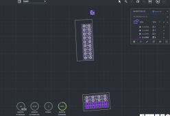
| Array Layout Readme | 2x9 portrait array on West facing house roof 4x4 landscape array on South facing garage roof |
| Three Line Diagram Readme | Garage array: Soladeck with fused combiner combining two strings of 8 panels. 10/2 FMC coming out from bottom of soladeck into attic space, come down wall of interior garage space (NW corner), enter PVC JB (covert to 10 awg THHN), go through PVC conduit underground to house basement. Inside basement will have PVC JB and convert back to 10/2 FMC to inverter. Might need a DC disconnect by garage? Not sure if that is necessary. House array: Soladeck with fused combiner combining two strings of 9 panels. 10 awg THHN in EMT across roof to edge and down along the side of the house. Enter house near meter and into inverter. Or can run two pairs of 12 awg wire and forego a combiner on the house roof (probably the cheaper option). |
This is where I get very confused. Read from the bottom up. (Names have been partially redacted). Why the heck is he saying I need 8 awg cable? Is my description of how I want to do the system not clear? I'm ready to submit an email to ask for a refund so I can go with a local route. I had a friend who works for a local solar company read the information below and he doesn't understand it either?
Alexander T · 12-14-2022 3:37:52am
You will use optimizers in this system. Max output ampacity (with 125%) is 15A*1.25=18.75A If we combite two strings into one (by parallel connection) we will have 18.75*2=37.5.Arthur (me) · 12-13-2022 9:24:09pm
Garage Home Run 1String A: 8 panels x 410w = 3,280w / 400v = 8.2A
String B: 8 panels x 410w = 3,280w / 400v = 8.2A
String A + B combined in fused combiner box = 6,560w / 400v = 16.4A
Output is 10 awg wire to inverter
House Home Run 2
String C: 9 panels x 410w = 3,690w / 400v = 9.2A
String D: 9 panels x 410w = 3,690w / 400v = 9.2A
String C + D combined in fused combiner box = 7,380w / 400v = 18.45A
Output is 10 awg wire to inverter
Home run 1 and home run 2 meet at the inverter. Home run 1 and home run 2 will each carry a max of 16.4A and 18.45A respectively.
I'm not sure how you're getting 37.5A being carried on 10 awg wire? It's only 16.4A from the garage array and 18.45A from the house array? They both meet at the inverter junction block.
Alexander T · 12-13-2022 12:36:14pm
You will use optimizers in this system. Max output ampacity (with 125%) is 15A*1.25=18.75A If we combite two strings into one (by parallel connection) we will have 18.75*2=37.5. We can not connect 18 pv panel into one string using cascade connectionArthur (me) · 12-13-2022 5:39:25am
Where are you getting the 37.5 amp current figure?410w panels x 18 = 7.38 kw / 400v = 18.45 amps?
Or am I understanding something wrong.
Alexander T · 12-13-2022 3:30:49am
If we combine two string we will have max. current 37.5A. Base ampacity for 10 awg cable is 40A and terminal amp is 35A. So we can not use 10awg for string combining. For string combining more better use 8 awg.Arthur (me) · 12-12-2022 9:01:08pm
Hi Alexander,Were you able to see this note as shown below?
Garage array:
Soladeck with fused combiner combining two strings of 8 panels. 10/2 FMC coming out from bottom of soladeck into attic space, come down wall of interior garage space (NW corner), enter PVC JB (covert to 10 awg THHN), go through PVC conduit underground to house basement. Inside basement will have PVC JB and convert back to 10/2 FMC to inverter. Might need a DC disconnect by garage? Not sure if that is necessary.
House array:
Soladeck with fused combiner combining two strings of 9 panels. 10 awg THHN in EMT across roof to edge and down along the side of the house. Enter house near meter and into inverter. Or can run two pairs of 12 awg wire and forego a combiner on the house roof (probably the cheaper option?).
To summarize:
Garage - 10 awg run for 16 panels (8 series, 2 parallel)
House - 10 awg run for 18 panels (9 series, 2 parallel)
Thanks,
Arthur
Alexander T · 12-12-2022 3:09:40pm
Hi Arthur,we need clarify with you cable size issue. We can connect into the inverter only three strings. According to your design PS system will have 4 PV strings. It's mean we should combine two strings into one before connection into the inverter. If we combine two string we will have max. current 37.5A. Base ampacity for 10 awg cable is 40A and terminal amp is 35A. So we can not use 10awg for string combining. For string combining more better use 8 awg.
Please inform us how we should proceed.
Thank you
Last edited:


