


Hi Gang.
Sorry my very first post here is troubleshooting but I've been using help from this site to get this up and running and felt like this would have been easy. Tripping on the final hurdle. Some background so you know where I'm at.
Inverter: Growatt SPH-5000TL BL-UP (Australian Model)
Batteries: 5 x Growatt ARK 2.5L-A1 (more coming)
Rpi3 B+
My own lying about 1 metre Ethernet cable
The correct CP2102 chip USB adaptor
I followed this link to construct everything

 www.instructables.com
Which i believe come from here.
www.instructables.com
Which i believe come from here.
I used a forum post from here to learn and successfully set VPP Mode.
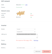
I'm pretty much stuck here on the SolarAssistant Configuration Page
USB ports: USB0 CP2102 USB to UART Bridge Controller
Status: No response. Retrying in 15s... - Settings
Reading from official solarassistant and other posts here. I've tried BOTH ports under my invertor 485-1 and 485-2
I have tried both pin 1 (red/white) and pin 4 (Blue) A+ on the USB adaptor. Current photo shows red/white (Red is hidden)
I'm attaching some pics...
EDIT: You do see the "tx" light flash intermittently through the casing of the USB adaptor.
EDIT 2: Growatt dongle with using Ethernet still attached!
Man, i gotta be close as i think i covered everything.
Sorry my very first post here is troubleshooting but I've been using help from this site to get this up and running and felt like this would have been easy. Tripping on the final hurdle. Some background so you know where I'm at.
Inverter: Growatt SPH-5000TL BL-UP (Australian Model)
Batteries: 5 x Growatt ARK 2.5L-A1 (more coming)
Rpi3 B+
My own lying about 1 metre Ethernet cable
The correct CP2102 chip USB adaptor
I followed this link to construct everything
Construction and Connecting SolarAssistant on a Raspberry Pi to Control and Monitor Your Solar Panel System
Construction and Connecting SolarAssistant on a Raspberry Pi to Control and Monitor Your Solar Panel System: Full detail on my main site here http://www.brettoliver.org.uk/Solar_Power/Solar_Power.htm SolarAssistant is software used to monitor and control your solar system in real time and can be...
www.instructables.com
I used a forum post from here to learn and successfully set VPP Mode.
I'm pretty much stuck here on the SolarAssistant Configuration Page
Inverter
Model: Growatt / Growatt SPHUSB ports: USB0 CP2102 USB to UART Bridge Controller
Status: No response. Retrying in 15s... - Settings
Reading from official solarassistant and other posts here. I've tried BOTH ports under my invertor 485-1 and 485-2
I have tried both pin 1 (red/white) and pin 4 (Blue) A+ on the USB adaptor. Current photo shows red/white (Red is hidden)
I'm attaching some pics...
EDIT: You do see the "tx" light flash intermittently through the casing of the USB adaptor.
EDIT 2: Growatt dongle with using Ethernet still attached!
Man, i gotta be close as i think i covered everything.
Attachments
![IMG_5598[1].JPG](/data/attachments/231/231850-2be6a6f1d8cb6df0c3ecfb8e24fd253a.jpg)
![IMG_5599[1].JPG](/data/attachments/231/231851-109d056ae6d6f6499b2ac419a020d4a6.jpg)
![IMG_5601[1].JPG](/data/attachments/231/231853-858500b6d8af8d108a5becafb1104ac1.jpg)
![IMG_5603[1].JPG](/data/attachments/231/231854-651cf4a2617c9872989ca8404e2312b2.jpg)
Last edited: