littlehuw
New Member
Hello all, thankful to have found this forum!
A bit of background, originally had done solar on RVs and wanted to carry that through to power the garden pond and garden lights.
That worked, and then included the washing machine and now looking to add the fridge and freezers on.
I get there are limits on expandability and we are most definitely nearing ours which would mean going to a 48v system.
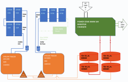
So where are we at. We have just got 2 x 375 panels and have purchased a second MPPT controller - see attached schematic.
Epever say they wont work together as they both have to be minimum 60A controllers to use their parrallel adapter.
Nick Seghers in his Off Grid Solar Power Simplified book says that they don't have to talk to each other to be able to work.
I also got a bit confused with how these then go into the battery breaker so have order two different ones as per the charge controllers.
So Question 1 Do I need the 2 Breakers or will both chargers go into the one and will that be the lower or the higher amp?
The battery people told me when asked about best power rating for the batteries to set at 56A or minimum 10% power for the inverter/charger (currently dumbed down to 42A on AC as it kept drawing too much and blowing the fuse, more about how its connected into the house I think!)
Question 2 Is there a setting to set the chargers to the same output amps or the maximum?
Question 3 Is there anything else I am missing?
Schematic doesn't show the earthing rod and cable which I am installing tomorrow before I faff with anything else. It has been very much a grow and learn and so far I've only blown up one 500w inverter!!! Currently the set up is first string of 2 x 375w and second string of 3 x 150w which we now know is over the capacity of the 40A controller but it didn't get installed until September last year so thankfully hasn't maxed it out. The 4 x 220ah batteries are set to 24v in series so hopefully giving us 2400watt hours. At the moment through the winter, the AC charger has kicked in during the night with very minimal draw on the battery side of things.
Anyhoo, will probably have more questions as the thread progresses.
Cheers for any help, gratefully received. Huw
A bit of background, originally had done solar on RVs and wanted to carry that through to power the garden pond and garden lights.
That worked, and then included the washing machine and now looking to add the fridge and freezers on.
I get there are limits on expandability and we are most definitely nearing ours which would mean going to a 48v system.
So where are we at. We have just got 2 x 375 panels and have purchased a second MPPT controller - see attached schematic.
Epever say they wont work together as they both have to be minimum 60A controllers to use their parrallel adapter.
Nick Seghers in his Off Grid Solar Power Simplified book says that they don't have to talk to each other to be able to work.
I also got a bit confused with how these then go into the battery breaker so have order two different ones as per the charge controllers.
So Question 1 Do I need the 2 Breakers or will both chargers go into the one and will that be the lower or the higher amp?
The battery people told me when asked about best power rating for the batteries to set at 56A or minimum 10% power for the inverter/charger (currently dumbed down to 42A on AC as it kept drawing too much and blowing the fuse, more about how its connected into the house I think!)
Question 2 Is there a setting to set the chargers to the same output amps or the maximum?
Question 3 Is there anything else I am missing?
Schematic doesn't show the earthing rod and cable which I am installing tomorrow before I faff with anything else. It has been very much a grow and learn and so far I've only blown up one 500w inverter!!! Currently the set up is first string of 2 x 375w and second string of 3 x 150w which we now know is over the capacity of the 40A controller but it didn't get installed until September last year so thankfully hasn't maxed it out. The 4 x 220ah batteries are set to 24v in series so hopefully giving us 2400watt hours. At the moment through the winter, the AC charger has kicked in during the night with very minimal draw on the battery side of things.
Anyhoo, will probably have more questions as the thread progresses.
Cheers for any help, gratefully received. Huw