diy solar

diy solar

Help with smart shunt wiring and additional improvements to safety

domscand

New Member
Joined
Jan 5, 2024
Messages
6
Location
Chicago
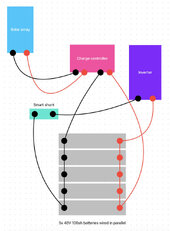
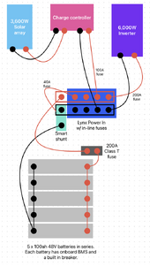
I've recently built an off grid home in Belize. The solar system was installed as part of a package and I had no control over the specific components, wiring etc. I'm now trying to understand the system top to bottom and begin making improvements to it starting with the installation of a smart shunt. I've created this diagram for the purposes of discussing the improvements to the system. My first problem is that the way I've wired the smart shunt between the negative battery terminal and the inverter, it is blind to the charge controller input coming into the opposite end of the battery bank and therefore only reports the power being used and not the charge coming in. The system currently has no fuses or busbars so my plan is to add a positive and negative busbar and update the connections for the inverter and charge controller to both connect at the bus bar, vs opposite ends of the battery bank, but wanted to confirm that wouldn't cause other problems before proceeding.

Related, I had trouble restarting the battery bank after having everything shut down to make this change which exposed a problem with either the wiring or components of this system. The installer said the restart sequence was "complicated" and came to do it themselves vs explaining it to me over the phone. When they arrived I understood why quickly as it involved reconnecting the last battery to the bank with a small wire from a cell phone charger slowly to avoid the current causing the BMS systems of each battery to start alerting which is what was happening to me when turning them back on as wired. After the last/top battery started with the connection with the smaller wire, they slowly connected the inverter/battery connection with the 2/0 wiring and everything remained running without issue. The question here is really just if the busbar changes will fix this as well or if there are additional safety changes I should make with a fuse on the positive connection and/or a disconnect switch as well.
 

Attachments

  • solar diagram.jpg
    solar diagram.jpg
    86.6 KB · Views: 41
As you said, in a normal configuration the shunt should sit between the battery bank and the negative busbar, that way it's "aware" of current from both the SCC and inverter.

When you have multiple batteries in parallel like this, it would also be smart to use a busbar and equal length wiring to parallel them. So, that would mean you have a pair of busbars dedicated to connecting the batteries, and a second set of busbars where your equipment connects to. In between these busbars is where your smart shunt would sit.

Someone smarter than me can correct me if I am wrong, but this is how I would change the system.
 
Do you think the lack of fuses and/or busbars is causing the crazy startup procedure?
No.
It sounds that when you reconnected the system , high inrush current into the inverter caused overcurrent protection in the battery BMS that shutdown the battery. The trick with the phone charger allowed the inverter capacitors to charge up. Thus once the batteries were reconnected there was no inrush current.
 
For the pre-charge resistor, I built mine based off this resource off the forum:


I find the BMS tripping on powering up an inverter odd.


What sized Inverter do you have in Watts?

What voltage is your system?

How many amps is your BMS?


When a BMS shuts off during inverter powerup, makes me think that the BMS may be too small for the inverter.

As you learn more from the forum, you'll be able to install things your installer missed.

There is a lot of freedom for an installer to do an RV build. I don't know of any code he needs to follow. Unfortunately, this leads to things like fuses not being installed among others. In a house build these types of things are looked at prior to the build with the plans and post build with the inspection.
=====
I don't know what info you need from the shunt, but a second shunt could be added to get data from the batteries.

When the sun is up and I'm pushing the inverter, my shunt at the battery could read charging 100 watts, but the inverter is actually pulling 2000 watts and my loads are 1900 watts to the inverter which coems from the SCC.
Thanks for the help!

- inverter is 6,000 watts
- batteries are "incell" branded 100ah 48v server rack with what I believe is a built in BMS within each of them (sorry if my terminology is incorrect on that). They are lithium ion.
- system voltage is 48v
- build is within a home not RV, but it is in Belize not the US or Canada so no code they needed to meet or anything like that so lots of room for improvement.
- my goal with adding the shunt which is a victron smart shunt with connection to solar assistant is to both locally and remotely monitoring the battery percentages without needing to physically go to the solar shed. For my immediate needs I'm at least able to do that with the voltage and determine the percentage charge roughly from that, but the smart shunt details outside of voltage are all completely out of sync since it is missing the PV charge input altogether.
 
- my goal with adding the shunt which is a victron smart shunt with connection to solar assistant is to both locally and remotely monitoring the battery percentages without needing to physically go to the solar shed. For my immediate needs I'm at least able to do that with the voltage and determine the percentage charge roughly from that, but the smart shunt details outside of voltage are all completely out of sync since it is missing the PV charge input altogether.
The Victron Shunt is Blue Tooth and that is limited range, but you can get a VRM cable to go WiFi.
- inverter is 6,000 watts
- batteries are "incell" branded 100ah 48v server rack with what I believe is a built in BMS within each of them (sorry if my terminology is incorrect on that). They are lithium ion.
- system voltage is 48v
I'm not sure how many batteries you have, or the BMS amperage in them, but I'm surprised the BMS trips.

I have used the Resistor Switch that was linked earlier for a battery bank rated at 13.6 kWh, 560 ah, 24 volt. My BMS did not trip before I installed that switch, but whenever I turned it on, there was quite the spark show.
 
The Victron Shunt is Blue Tooth and that is limited range, but you can get a VRM cable to go WiFi.
Yep, I actually already have the VRM USB cable and have it hooked up to Solar Assistant and working correctly. Obviously this is all massively hindered by the fact that I have the smart shunt wired incorrectly and it is only picking up the battery output and not the input from the charge controller, but I think I now know exactly what to do to fix that with switching to a positive and negative bus bar and moving the connections for the inverter and charge controllers over to that vs directly to the batteries which will allow me to move the shunt between the battery bank negative and the busbar and have it able to actually see/monitor everything in and out successfully.
I'm not sure how many batteries you have, or the BMS amperage in them, but I'm surprised the BMS trips.

I have used the Resistor Switch that was linked earlier for a battery bank rated at 13.6 kWh, 560 ah, 24 volt. My BMS did not trip before I installed that switch, but whenever I turned it on, there was quite the spark show.
I have 5x 100AH batteries at 48 volt (24 kWh total if my math is correct). I didn't actually see sparks just turning the batteries on so maybe the BMS is just really sensitive/aggressive within the batteries? Basically if I turned just 1 on, it booted up with no issues but as soon as I started a second they started freaking out. When the installers were there and did the start up sequence with the phone charger there were actually sparks, but still very limited compared to what it sounds like you had without the resister. I'm thinking that if I build that switch following the 48 volt diagrams that might be my answer to avoiding this problem.
 
Fix the Smartshunt wire if by just moving the one cable.
The cable from the solar charge controller directly to the battery- needs to be moved from the battery to the “load” side of the shunt.

Kill the solar power to the Solar Charge Controller first (dark or solar cutoff switch or - if Victron, in the app you can turn it off).

You could probably do it with the battery and inverter live (get gloves that will prevent shock), also turn off all loads of 120v and if possible switch inverter to off - just for the 20 seconds to move the wire. The inverter should remain charged- especially if you do it with the batteries live.

*****
For the precharge, you could make yourself a little 48v battery or get a resistor or light bulb - like many do here.

*****
I really like the Victron PowerIn’s with fuses (see YouTube to add fuses). They are expensive but good and you get a fuse holder for each line.

Make one for a battery bus bar w/fuses (all batteries connect directly to it with equal cables), then your shunt on negative and a class T fuse on positive (and maybe a system on/off switch).

Then to a load/charger PowerIn bus bar w/fuses. So each item inverter,SCC, etc will have it own fuse.

Good Luck!
 
I have 5x 100AH batteries at 48 volt (24 kWh total if my math is correct). I didn't actually see sparks just turning the batteries on so maybe the BMS is just really sensitive/aggressive within the batteries? Basically if I turned just 1 on, it booted up with no issues but as soon as I started a second they started freaking out. When the installers were there and did the start up sequence with the phone charger there were actually sparks, but still very limited compared to what it sounds like you had without the resister. I'm thinking that if I build that switch following the 48 volt diagrams that might be my answer to avoiding this problem.
If the BMS is tripping when hooking a battery together, that could point to a mismatched battery. One high and one low.

The procedure for that would be to charge them individually and turn them on. That would prevent the high current inrush as high battery tries to quickly balance the other.
 
Fix the Smartshunt wire if by just moving the one cable.
The cable from the solar charge controller directly to the battery- needs to be moved from the battery to the “load” side of the shunt.

Kill the solar power to the Solar Charge Controller first (dark or solar cutoff switch or - if Victron, in the app you can turn it off).
I thought this might work, but then I was worried about how the positive input from the charge controller would be wired so differently and to the opposite end of the battery bank. It’s good to know I wasn’t crazy for thinking this small change could work. I’ll just do the busbar and fuse changes all at once.
You could probably do it with the battery and inverter live (get gloves that will prevent shock), also turn off all loads of 120v and if possible switch inverter to off - just for the 20 seconds to move the wire. The inverter should remain charged- especially if you do it with the batteries live.

*****
For the precharge, you could make yourself a little 48v battery or get a resistor or light bulb - like many do here.

*****
I hadn’t heard of the little battery or light bulb tricks yet. I’ll look into both, but I think I’m going to create a switch with a resister in it as another user suggested.
I really like the Victron PowerIn’s with fuses (see YouTube to add fuses). They are expensive but good and you get a fuse holder for each line.

Make one for a battery bus bar w/fuses (all batteries connect directly to it with equal cables), then your shunt on negative and a class T fuse on positive (and maybe a system on/off switch).

Then to a load/charger PowerIn bus bar w/fuses. So each item inverter,SCC, etc will have it own fuse.
This sounds like a really great tip to get in the additional fuses without a ton of extra work and wiring. I’ll look into PowerIn. Thank you!
Good Luck!
 
Buy a 300A circuit breaker and connect 1 end to the battery bank, the other to the smart shunt and then land both charge controller and inverter on the other end of the shunt.
You can build the pre-charge resistor/lamp circuit across the breaker. Breaker off, hit the pre-charge switch until the light dims to off, turn on the breaker.
A picture of your present setup will help us to guide you.
 
Ok, this is my planned update diagramed out:
  1. Get a lynx power in and update it for in-line fuses.
  2. Move the charge controller and the inverter connections to the power in. This should set the smart shunt up to be correctly wired and be able to monitor all charging and discharging properly.
  3. Add a 200A Class T fuse (using 2/0 wiring in the system currently) between the battery bank positive and the lynx power in.
  4. Add a 200A fuse for the inverter connection and a 100A fuse for the charge controller within the lynx power in.
  5. Get a resister or bulb for pre-charging, but considering skipping the battery cut off since the batteries have individual breakers and can easily all be switched off. I'd then do the pre-charging just between the battery and the fuse or the battery and the shunt.
 

Attachments

  • Wiring plan.png
    Wiring plan.png
    216.4 KB · Views: 11
Back
Top