diy solar

diy solar

How to achieve up to spec battery compression?

jazzy

New Member
Joined
Jul 4, 2024
Messages
4
Location
Spain
Let me come back to the confusing matter of compressing prismatic LiFePo4 cells.
Let's focus on the thread subject and not diverge into whether you should or shouldn't compress.

Manufacturer recommendation is to compress with the force of 300kgf +/- 20kgf
That means 2941 N over the surface area of the cell, correct? (1kgf=9.807N)
The cell I have in mind is 204mm by 174mm that's equals to 0.035m2
So the pressure is 2941N/0.035 ~84kPa
or 12.2 psi which is in accordance with discussions on similar threads

12 psi doesn't seem like much but that is 12 pounds on every square inch, over entire surface of the cell it ads up to 300kg or 660 pounds sitting on top of the cell (covered with rigid plate so the compressions is distributed evenly)
That's not hand squeeze like suggest on some threads that's 4 adults sitting there, am I right?

Any ideas how to achieve the correct, pressure in a budget limited, DIY environment?

After browsing through forums I understand that calculating compression force from torque gives ~40% uncertainty, far to high to meet manufacturer recommendation.

Any input welcome
Cheers
 
I thing the idea is to use threaded rods and metal plates. The rods have a "threads per inch ". Add springs with a known compression rating, and you can calculate how many turns of the nut to produce a certain level of force.

If you have 4 rods, that is 150# of force on each rod to make 600#. But, like a pully, you are putting that pressure on each side, so is that double?
 
Let me come back to the confusing matter of compressing prismatic LiFePo4 cells.
Let's focus on the thread subject and not diverge into whether you should or shouldn't compress.

Manufacturer recommendation is to compress with the force of 300kgf +/- 20kgf
That means 2941 N over the surface area of the cell, correct? (1kgf=9.807N)
The cell I have in mind is 204mm by 174mm that's equals to 0.035m2
So the pressure is 2941N/0.035 ~84kPa
or 12.2 psi which is in accordance with discussions on similar threads

12 psi doesn't seem like much but that is 12 pounds on every square inch, over entire surface of the cell it ads up to 300kg or 660 pounds sitting on top of the cell (covered with rigid plate so the compressions is distributed evenly)
That's not hand squeeze like suggest on some threads that's 4 adults sitting there, am I right?

Any ideas how to achieve the correct, pressure in a budget limited, DIY environment?

After browsing through forums I understand that calculating compression force from torque gives ~40% uncertainty, far to high to meet manufacturer recommendation.

Any input welcome
Cheers
You can use poron 4701 foam sheets and compress it ~25% from original thickness to achieve the target psi.
 
Let hime come back to the confusing matter of compressing prismatic LiFePo4 cells.
Let's focus on the thread subject and not diverge into whether you should or shouldn't compress.

Manufacturer recommendation is to compress with the force of 300kgf +/- 20kgf
That means 2941 N over the surface area of the cell, correct? (1kgf=9.807N)
The cell I have in mind is 204mm by 174mm that's equals to 0.035m2
So the pressure is 2941N/0.035 ~84kPa
or 12.2 psi which is in accordance with discussions on similar threads

12 psi doesn't seem like much but that is 12 pounds on every square inch, over entire surface of the cell it ads up to 300kg or 660 pounds sitting on top of the cell (covered with rigid plate so th
I thing the idea is to use threaded rods and metal plates. The rods have a "threads per inch ". Add springs with a known compression rating, and you can calculate how many turns of the nut to produce a certain level of force.

If you have 4 rods, that is 150# of force on each rod to make 600#. But, like a pully, you are putting that pressure on each side, so is that double?
One can calculate the force from a torque applied to the nut, using torque wrench so you tight to x Nm to achieve correct pressure, however like I mentioned it gives high error results. (There's enough talk about out there so won't go into details)
Then you need to understand how multiple rods affect the torque needed, which I did not look into since using torque seems unreliable
 
One can calculate the force from a torque applied to the nut, using torque wrench so you tight to x Nm to achieve correct pressure, however like I mentioned it gives high error results. (There's enough talk about out there so won't go into details)

using springs avoids the error of estimating pressure from torque on nuts.
 
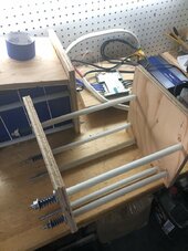
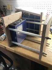
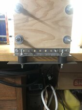
I used valve springs from an auto parts supplier. Stuck my bathroom scale on my hydraulic press, used the press to compress the springs to 150lbs of force, then measured the length of the spring at that compression. Put the springs on threaded rods with nuts and big washers, then cranked them down until the springs were the right length. Angle iron and two layers of 3/4" plywood to even out the force. 150lbs x 4 rods and springs = 600lbs. Close enough for me.
 
Let me come back to the confusing matter of compressing prismatic LiFePo4 cells.
Let's focus on the thread subject and not diverge into whether you should or shouldn't compress.

Manufacturer recommendation is to compress with the force of 300kgf +/- 20kgf
That means 2941 N over the surface area of the cell, correct? (1kgf=9.807N)
The cell I have in mind is 204mm by 174mm that's equals to 0.035m2
So the pressure is 2941N/0.035 ~84kPa
or 12.2 psi which is in accordance with discussions on similar threads

12 psi doesn't seem like much but that is 12 pounds on every square inch, over entire surface of the cell it ads up to 300kg or 660 pounds sitting on top of the cell (covered with rigid plate so the compressions is distributed evenly)
That's not hand squeeze like suggest on some threads that's 4 adults sitting there, am I right?

Any ideas how to achieve the correct, pressure in a budget limited, DIY environment?

After browsing through forums I understand that calculating compression force from torque gives ~40% uncertainty, far to high to meet manufacturer recommendation.

Any input welcome
Cheers

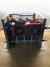
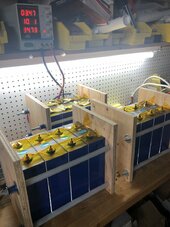
Not using springs in compression fixture. Just using yellow pine wood 1 inch x 10 inch cut to length and four 1/4 inch course threaded rods with 1/4 inch nuts & washers on the 8s Lifepo4 battery packs.

This is Info I used and torqued a little less at 5 Inch Pounds with a torque wrench at about 3.2 to 3.3 volts charge in each cell.

The spec from EVE was 300 KG force which rounds off to 660lbs. Battery face is approx 6.85"x 7.874" = 53.94 sq inches
660lbs/53.94sqin=12.23 lbs per sq inch
Divide 660 by 4 bolts that's 165 lbs Axial (clamping) force per bolt.
Using 4 course 1/4 in threaded rods that should equate to roughly 8 INCH pounds torque per bolt. Realistically, that's a snug twist of the wrist on a regular nut driver for the average build mechanic.

In the future when rebuilding the battery packs will probably add something like 1/4" steel plates to the 1 inch x 10 inch yellow pine wood for added strength.

Hope it helps..
 
Last edited:
I don't compress the cells in my DIY packs, but if I did I would want the expansion to be isolated to the spaces between each cell, and the bus bars don't transfer the loads to the termals.
This would require using an elastic material between each cell - and as Matt already said there are soft-ish sheets for this such as Poron 4701-43 (spec sheet attached) - although the "43" is called up for "EV" the stress-strain curve seems too low (ie not 12psi) but they do make many other grades of Poron 4701 each with different resilence.
The material has a relatively flat stress-strain curve in the 10-55% compression range, and this would be the zone to use for the cells, such that low SOC is low %-compressed, and higher SOC is moderate-% compressed, trying to follow the 10%-55% range.
Could be fun project to play with various starting (low SOC) compression of the foam, and test how much additional compression-% is achieved by charging to 100% SOC. Also testing and measuring the actual ideal thickness of foam needed to remain in the linear part of the stress-strain curve while minimizing the total thickness of foam sheets needed since the foam adds considerable distance to the overall length of a pack when you are putting 8-16 cells in a long row.
Someone should do this and post the results for the rest of us! ;)
 

Attachments

  • PORON-4701-43-EVExtend-Data-Sheet.pdf
    294.7 KB · Views: 1
I don't compress the cells in my DIY packs, but if I did I would want the expansion to be isolated to the spaces between each cell, and the bus bars don't transfer the loads to the termals.
This would require using an elastic material between each cell - and as Matt already said there are soft-ish sheets for this such as Poron 4701-43 (spec sheet attached) - although the "43" is called up for "EV" the stress-strain curve seems too low (ie not 12psi) but they do make many other grades of Poron 4701 each with different resilence.
The material has a relatively flat stress-strain curve in the 10-55% compression range, and this would be the zone to use for the cells, such that low SOC is low %-compressed, and higher SOC is moderate-% compressed, trying to follow the 10%-55% range.
Could be fun project to play with various starting (low SOC) compression of the foam, and test how much additional compression-% is achieved by charging to 100% SOC. Also testing and measuring the actual ideal thickness of foam needed to remain in the linear part of the stress-strain curve while minimizing the total thickness of foam sheets needed since the foam adds considerable distance to the overall length of a pack when you are putting 8-16 cells in a long row.
Someone should do this and post the results for the rest of us! ;)
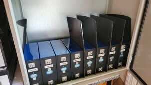
I'm using 4701-40 and it's definitely an issue getting them to fit in this 24*24 cabinet. Prob have to just use fr4 sheets on the outer cells to get them in there.

20240702_163123.jpg


Screenshot_20240705_083942_Chrome.jpg

 
Last edited:
I was tempted, but the cases I built would all need to be modified. This made me think about combining two projects: I would like to upgrade my DIY pack cases from plywood to steel, and the resulting thinner material should allow the space I need for the foam. But too busy with other projects right now, has to wait! LOL.
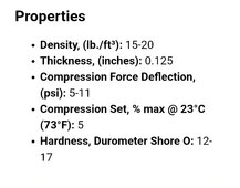
If the compression force target is 12psi, why use foam with 5-11psi range stress-strain curve?
ideally would want the 'flat' part of the curve to be very close to 12psi. ie the 4701-50 or 4701-60
Thats a firmer material apparently designed for "high energy impacts and gasketing" moreso than battery pad applications.


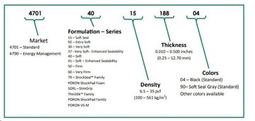
Here's the decoder, I'm using 4701-40-20125-04
Screenshot_20240705_091554_Chrome.jpg

Personally I would rather err on the lesser side of the compression tipping point.
 
If we need 12psi compression but we use a material with only 5psi stress-strain why bother with it at all?
Wel if the cells do set out.
Its blokt by wat your construction is.
But i think you are correct.
See the compleet battery setup from battery company.
Its just same plastic like a lead battery.

But than again people that use full 100% day by day with real fast charge i do understand why this is done
 
Rated die springs. I have mine packs at 640lb. I have been using these for 2.5 years in an off road environment mounted on 1” vibration dampers with no issues.

2AC86E66-14A9-47FC-8978-4A80F8A23074.jpegB0E2FC4B-6EF4-43AD-B2BD-89EC6888C671.jpeg
98F5B678-7DDC-4718-997B-7E2197EB3933.jpeg4FF86F69-AD0E-4AF0-ABE6-47B4DE4BB1D5.jpeg
58B3D09C-8E0B-4A94-BA87-8BDCB7AD42EF.jpeg
 
I used valve springs from an auto parts supplier. Stuck my bathroom scale on my hydraulic press, used the press to compress the springs to 150lbs of force, then measured the length of the spring at that compression. Put the springs on threaded rods with nuts and big washers, then cranked them down until the springs were the right length. Angle iron and two layers of 3/4" plywood to even out the force. 150lbs x 4 rods and springs = 600lbs
 
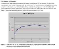
Below there's an interesting research paper on li ion cells (unfortunately not lfp) compression.
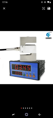
I like the idea of using bathroom scale, I just found a weight sensor with display for €60 on ali.
 

Attachments

  • Effects_of_Mechanical_Compression_on_the_Aging_and.pdf
    1.7 MB · Views: 3
  • Screenshot_20240706-171658.png
    Screenshot_20240706-171658.png
    175.8 KB · Views: 2
I am gonna ask, why don't those of you that build batteries also put something smooth on the bottom? Would have to be fixed at one end and free on the other, but would provide a smooth surface for the batteries to rest on/slide on? Maybe a couple of pieces of aluminum topped with the insulator used between. Then you could use the free part that extends through the endplate as a guide for expansion/etc. Might even be able to put a sensor on it to give you a digital readout. One on each side would tell you even expansion/tension.
 
It would be better to use the isolation sheets between each cell to provide the compression rather than springs on rods approach, to limit the loading on each bus-bar and terminal.
The effect becomes greater as we increase the number of cells in one row, for my own DIY packs this is 8 cells in two rows. Even a small 0.5mm per cell swelling becomes 4mm across 8 cells. For the members putting a single row of 16 cells, this would be 8mm (about 5/16 of an inch) across the entire pack.
Compare this with using resilent sheets with compression Stress-Strain response in the 12psi range, each cell has it's own space available without the accumulating affect across multiple cells all adding to stress on the terminals. Yes we see a lot of 'flexible bus bars' most are just a bend in a regular bus and it can only flex if the terminals apply the force to them (not ideal).

Thinking about rebuilding my DIY cases in steel, and if I do, I will be using resilient sheets as spacers as well, may as well use a 12psi rated sheet to match the cell compression data we have IMHO.
 
I am gonna ask, why don't those of you that build batteries also put something smooth on the bottom? Would have to be fixed at one end and free on the other, but would provide a smooth surface for the batteries to rest on/slide on? Maybe a couple of pieces of aluminum topped with the insulator used between. Then you could use the free part that extends through the endplate as a guide for expansion/etc. Might even be able to put a sensor on it to give you a digital readout. One on each side would tell you even expansion/tension.
If you stack 16cells in a row and try to push from one end, how hard do you have to push to move the far cell? I think too many overlook the friction created by the weigh of the cells against whatever materiel they rest upon. With foam sheets between each cell, I'd think this issue might be alleviated, but using springs, or other end clamp methods, with the cells sitting on a course surface, how evenly is the compression force distributed throughout the line of 16cells?

For those of you using the Poron, or other foam, where did you purchase and how expensive was it? I'm looking at rebuilding a more compact battery cabinet and thinking of going this route.

... oh, what thickness?
 
Last edited:
If you stack 16cells in a row and try to push from one end, how hard do you have to push to move the far cell? I think too many overlook the friction created by the weigh of the cells against whatever materiel they rest upon. With foam sheets between each cell, I'd think this issue might be alleviated, but using springs, or other end clamp methods, with the cells sitting on a course surface, how evenly is the compression force distributed throughout the line of 16cells?

For those of you using the Poron, or other foam, where did you purchase and how expensive was it? I'm looking at rebuilding a more compact battery cabinet and thinking of going this route.

I'm using fr4 sheets for insulation underneath the cells. I believe that's best practice, even though the bottom "pad" of my rept280 seems pretty solid.
 
It would be better to use the isolation sheets between each cell to provide the compression rather than springs on rods approach, to limit the loading on each bus-bar and terminal.
The effect becomes greater as we increase the number of cells in one row, for my own DIY packs this is 8 cells in two rows. Even a small 0.5mm per cell swelling becomes 4mm across 8 cells. For the members putting a single row of 16 cells, this would be 8mm (about 5/16 of an inch) across the entire pack.
Compare this with using resilent sheets with compression Stress-Strain response in the 12psi range, each cell has it's own space available without the accumulating affect across multiple cells all adding to stress on the terminals. Yes we see a lot of 'flexible bus bars' most are just a bend in a regular bus and it can only flex if the terminals apply the force to them (not ideal).

Thinking about rebuilding my DIY cases in steel, and if I do, I will be using resilient sheets as spacers as well, may as well use a 12psi rated sheet to match the cell compression data we have IMHO.
I understand you are trying for the ideal 12 psi sheet but you'll prob have to buy a roll of it yourself if you are looking for the -50 or -60 foam type. I'm not sure about the Rogers but I think st gobain had similar pad material and their minimum order was $300 something
 

diy solar

diy solar
Back
Top