diy solar

diy solar

Hybrid grid/solar system

RockOn

New Member
Joined
Aug 29, 2023
Messages
15
Location
Chester, CT
Thanks in advance folks for any comments.
Learning solar for both my house and my boat.

Hybrid grid and solar for my house BUT NOT tied to grid for any excess to flow back to utility.

Goal is to actively learn and in doing so cut a little off my electricity bill so here are the guidelines:
- 240v circuits will stay on grid power off the 200amp main panel
- 120v circuits will all be able to be on grid or solar through (2) 10 circuit transfer switches

Will try to run all non-240v circuits with my solar panels and batteries to see how much load I do end up with and if needed keep some on grid unless power outage.
Will obvious not be using any window air conditioners or the like either.

Attached is diagram but here is some info:
- (16) 325 watt panels in 2 (8) panel arrays - so each string is 368v, 2600 watts, 10.9 amps (can expand to twice this size as needed)
- (2) 10 circuit Reliance Transfer Switches for the 120v circuits (15 and 20 amp)
- (2) 3000watt 48v or 24v Hybrid MPPT controller/inverters (or also looking at one larger 5000 watt unit to feed both switches)
- (4) 48v 100ah LiFePo batteries or (4) 24V 200 batteries (20,480 watts)

I know panel array size not matching Inverter is breaking one rule if thumb, but would think based on battery bank size that this will be ok as both MPPT will feed a single bank and I can expand if/as needed.

I plan to use neutral/grounding scheme on page 2 as I may not run AC IN to the MPPTs and just leave them stand alone just connected to charge from solar.
 

Attachments

  • Solar Electrical Set-Up.pdf
    352.7 KB · Views: 14
(2) 3000watt 48v or 24v Hybrid MPPT controller/inverters (or also looking at one larger 5000 watt unit to feed both switches)
know panel array size not matching Inverter is breaking one rule if thumb
Typically “it has been said” that overpanelled systems by 10-20% is ok but that seems like a lot.

And as far as 3000W hybrid?
A 6000W LV6548 from MPP is 4000W x 2 mppt controllers built in, AND will sustain your alluded to loads with headroom. At ~46W idle consumption it’s not catastrophic.
10 circuit Reliance Transfer Switches for the 120v circuits
Why not just use the internal transfer switch of the hybrid inverter? Set it and forget it, and you are in business.
 
Typically “it has been said” that overpanelled systems by 10-20% is ok but that seems like a lot.

And as far as 3000W hybrid?
A 6000W LV6548 from MPP is 4000W x 2 mppt controllers built in, AND will sustain your alluded to loads with headroom. At ~46W idle consumption it’s not catastrophic.

Why not just use the internal transfer switch of the hybrid inverter? Set it and forget it, and you are in business.
I won't over panel too much due to the VOC limit (I know I can over panel for AMPS)
If the panels are 325watt, 46v and 10amps, I can get 6S2P per unit (24 panels 7,800) set up which would be 276v / 20amps per MPPT.
This would be supported by a 6000W LV6548 unit as well ofcourse with the 2 PV of 4,000).

For a unit with say 5,500 watt PV max / 500 VC max and 1 PV input, I'd only be able to do 9S2P (18 panels 5,850 watts)

And at $600-700 per 3000W unit of $1,200-1,500 for a single unit, pretty much equal costs.
But, one 6000W doesn't meet one the objectives is to have redundancy if a unit goes down but I like that unit (6000watt and 2 PV in).

I thought about powering the whole panel through the Gen interlock, but then I can't run my 240v appliances on grid while keeping most everything else off grid until I need to switch it back. Would like to be able to toggle specific circuits back to grid if I need to.
 
do you have any pics of your current main panel and location where you would be installing the inverters and batteries ? same building ? how far apart ?

I would not design a system for only 120v loads. there will come a point after you install that you will wish to expand.

it might be that on some days, your batteries will be full, the sun shining, 120v loads covered and you will be paying to run 240v loads at the same time your system is idling down.

you are spending good money and need to plan for future best as you can.

I would suggest a 125 amp subpanel for the solar loads and none of those gen transfer switches with 2 small inverters
 
Don't have a pic but its a std 200amp Square-D type panel.

Understood, on later regret without having 240v option, but with no transfer switch I lose the option of putting specific circuits on grid if needed unless I turn off the whole subpanel.

There was a lot of thought on a larger single 120/240v split phase inverter vs this transfer switch set-up.
But having the whole panel on PV or not, didn't meet my desire to be able to power specific circuits as needed.
Only appliances on 240v are Range/Oven, Clothes Dryer, Hot Tub, and Water Heater.

I have a 10 gallon 120v 2000 watt WH plumbed in line for backup so in a gird failure or emergency situation, I still have all house systems required covered off the 120v transfer switch.

If I did a 125 amp subpanel, is there a way to wire for what I am trying to do or is that whole panel basically on solar or not?
If is a binary situation, then I would rather lose day time PV excess than lose the flexibility to control the circuits.
 
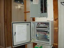
I run my home using a transfer control box similar to your Reliance proposal. I decided to build my own because I switch neutral and the Reliance panel does not do this. Because I run only 120vAC for most of my needs it does allow me to pick and choose when a circuit is grid powered or on the 3kW AIO (I actually have 2). This proved handy earlier on when I did not have as much solar and battery for loads like the A/C. My 30G HW tank I rewired it to 2000w 120vAC and can switch it to the AIO if extra solar is available, but can run it on grid otherwise. My only 240vAC loads are the electric Range, Clothes Dryer and electric heat. The Range is rarely used by me since I have countertop devices. The dryer is supplemented by a clothes line and the electric heat is only used when my woo stove or pellet stove is impracticable due to not being home.
 

Attachments

  • P1010012_v1.JPG
    P1010012_v1.JPG
    230.1 KB · Views: 7
ok great thanks so sounds like my plan has some precedent and is very similar.
I already have (2) 10-circuit transfer switches that will accommodate all my 120v mail panel circuits for complete flexibility on what is driven by PV.

Based on what I have seen, why do you switch Neutral and not wire to main breaker panel where the Neutral/Ground bond is?
Will my wiring work if I take the transfer switch N and G back to the main panel if I wire per one of the options from my file?
 
Because my AIO bonds NG when operating off inverter for AC out. No easy way to disconnect. Switching neutral insures there is no loops that running a common neutral could introduce.
 
I have a couple of hybrids LVX6048WP. I'm running them off grid but able to accept power fed from grid.
You would need four of them running in parallel to feed back 100 amps split phase 240 volts to your panel automatically switching from pv to batteries or grid. A hybrid allows combinations of those sources. I don't run a generator so I'm not sure how well that input works.

There is a new MPP 10 kw hybrid. I haven't seen any reviews yet. Two of those might handle all your 120/240 loads.

The advantage to going that way is being able to keep panel wiring as is and use excess solar for your 240 volt loads when it's available. These hybrids are pretty flexible if you want to add more pv or 48 volt batteries later on.

The disadvantage may be cost depending on the price of the reliance breakers. You may also want a transfer switch around the inverters for troubleshooting or maintenance.
 
Thank you both. Yes understand to make sure that I can kill the internal inverter NG bond if I wire the way that I show.

As far as 240v load - I don't care or need it and from what I have seen, a lot more expensive for 120/240v split phase capable units.
Also want to be able to swap AC inverter out wires to transfer switches in the event one unit goes down (redundancy). Transfer switch cost is a sunk cost as I already have them and without them, I can't toggle the load off the main panel circuit by circuit.

So really feedback on my schematic is what I'm looking for, but all good input and I appreciate it.
 
Back
Top