diy solar

diy solar

Off grid hybrid inverter SUB mode safety

Mayfield

New Member
Joined
Feb 28, 2024
Messages
7
Location
West Lancashire
Hello,
This is my first post so apologies if i am in the wrong place or asking a regular simple question. Having only ever used a car forum for 20 years I know how annoying it can be when a newbie asks a very basic question.
I have installed a 5kw Iconica hybrid off grid inverter with 3.6KW panel array. I am still running on some test lead acids until i splash out on some proper lithium batteries. Everything worked great out of the box. Set it going last May. It came in SBU mode doing fine over the summer whilst i was working on the property. Upon moving in I discovered the SUB mode. After reading the manual i reprogrammed to SUB. The unit voltage matched, synchronised and paralled with the utility. Being right at the side of the pole mounted rural transforner we sit at around 253 volts so i lifted the inverter voltage from 230 to 240 to lessen the voltage match movement. Having been in the property now for about 6 months I have obeserved the SUB mode doing what it says. Running in parallel using solar when available suplimented by the utilty. Or running on utility during night time.
Being from a generator background i am aware of the protection required to comply with utilty parallel. G59/G99 in UK and I believe G98 and G99 for solar grid tie.
Before I decided to fit my own system I was frustrated trying to find out about "grid tie" and "off grid" and was basically being told they are either one or the other. In my mind this is not the case. Even with SBU mode there is utilty support. I was adamant I was not going to be grid tied giving away units for next to nothing. Hence decision to go off grid falling back to utility.

So my question:
knowing that permission is required from DNO and certification of compliance to grid tie presumably some form of rocof type vector shift fast acting disconnect protection device is required. So were does that leave us with the scenario described above with an off grid hybrid inverter set in SUB mode running along with the grid.
I know it always sits in forward power to lessen the chance of any utilty export or reverse power. Upon failing the utilty feed to the inverter it momentarily drops the load to disconnect safely. I see some expensive inverters appear to have compliance approval.

How is such a system as mine viewed by the DNO.

Cheers Mike
 
Last edited:
Welcome!

You will need G99 application and approval from your DNO if the inverter is grid-tied. The inverter will also need to be G99 certified which you can check on the ENA Type Test register.

However, from your description, I'm not sure you have a grid-tied configuration? Can you post a simple schematic to show the connectivity between grid, CU and inverter? To me it sounds like you have an off grid configuration with just back up from grid, but no grid-tie in terms of inverter's output being in parallel with the incoming DNO supply?
 
Last edited:
Out of curiosity, have just scanned the user manual for your inverter. As far as I can see, there is no ability for the inverter's AC-generated output (from battery or PV) to connect to the DNO grid supply. All your loads are provided either by the inverter or switched in bypass mode from the grid. If my understanding is correct, then it is not grid-tied and hence does not fall into G99 compliance territory.

However, my reading of the spec does not fit with your comments where you say...
Running in parallel using solar when available suplimented by the utilty
and
I was frustrated trying to find out about "grid tie" and "off grid" and was basically being told they are either one or the other. In my mind this is not the case. Even with SBU mode there is utilty support.
Can you explain those comments a bit more?

On a separate note, 253V is right at the very maximum allowable voltage the DNO can supply under ESQCR 2002 regulations. Personally I'd be monitoring the voltage, especially at night when there is less load on the grid to make sure it doesn't exceed 253V.

If it does, then call the DNO's emergency helpline and report the issue. They should fix that either by tapping down a couple of taps on the secondary side of the LV transformer (2.5% per tap, IIRC) or replacing the transformer if it is past its best-before date! That will then reduce the voltage difference between your grid and inverter supply.
 
Welcome!

You will need G99 application and approval from your DNO if the inverter is grid-tied. The inverter will also need to be G99 certified which you can check on the ENA Type Test register.

However, from your description, I'm not sure you have a grid-tied configuration? Can you post a simple schematic to show the connectivity between grid, CU and inverter? To me it sounds like you have an off grid configuration with just back up from grid, but no grid-tie in terms of inverter's output being in parallel with the incoming DNO supply?
Thanks for your reply. My first reply. Will reply to second. Not used to this yet. I will post a diagram. I do not have a grid tied system. It is as you say an off grid system. No paralleling of the output. Just grid back up to the all in one combined box of tricks described as a hybrid off grid unit.
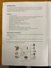
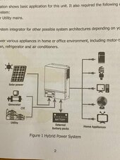
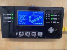
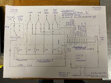
Please see shot of screen display, hand drawn diagram of my system and couple of shots of pages of little manual. You can see it is effectively in bypass with local grid volts input/output with the sòlar contributing onnthe load side.
 

Attachments

  • IMG_3080.jpg
    IMG_3080.jpg
    62.1 KB · Views: 13
  • IMG_3079.jpg
    IMG_3079.jpg
    68 KB · Views: 12
  • IMG_3077.jpg
    IMG_3077.jpg
    106.4 KB · Views: 13
  • IMG_3078(1).jpg
    IMG_3078(1).jpg
    247.8 KB · Views: 9
Out of curiosity, have just scanned the user manual for your inverter. As far as I can see, there is no ability for the inverter's AC-generated output (from battery or PV) to connect to the DNO grid supply. All your loads are provided either by the inverter or switched in bypass mode from the grid. If my understanding is correct, then it is not grid-tied and hence does not fall into G99 compliance territory.

However, my reading of the spec does not fit with your comments where you say...

and

Can you explain those comments a bit more?

On a separate note, 253V is right at the very maximum allowable voltage the DNO can supply under ESQCR 2002 regulations. Personally I'd be monitoring the voltage, especially at night when there is less load on the grid to make sure it doesn't exceed 253V.

If it does, then call the DNO's emergency helpline and report the issue. They should fix that either by tapping down a couple of taps on the secondary side of the LV transformer (2.5% per tap, IIRC) or replacing the transformer if it is past its best-before date! That will then reduce the voltage difference between your grid and inverter supply.
Thanks for reply SeGal. Please see my first reply. This is the part that confuses me. The system us running in bypass with parallel contribution from the PV system. I know it does this as when i load it with loading beyond the solar PV available power the remainder is contributed from the grid.

Re:explaining my comment about either grid tie or off grid. Speaking to a few boffins at solar suppliers i was told it was either one or the other. Basically what the hell was i talking about. Silly boy type of attitude.
However finding the SUB mode tells me different. I am and have been running together.
Re high voltage, good point, i do have concern. I no longer have a max min expensive fluke meter but will look tonight. Several times. I think i have seen 256. The hv lines pass our garden and the pole mounted transformer is in our garden.
Looks to be 40 to fifty years old. Probably tapped for the people at the remote end of the LV side. Several farms at the very end of a long lane. It is an ugly brute so would contact them.
Just a point for anyone looking at my crappy hand drawn diagram. I have 4 din rail mounted changeover switches in an enclosure for moving the following heavier loads from solar ourput to direct grid supply - cooking hob, oven, ring main 1 and ring main 2.
I am running with just the ring mains of these 4 loads on solar but if I am able to expand to a second inverter to double the inverter rating i would be able to simply switch over.
I purchased an inverter with parallel capabilty.
 
Last edited:
How are you verifying that it is supplementing grid? I don't at all see compelling evidence of this. Because what you observe could simply be the inverter matching frequency and voltage with grid, WITHOUT parallel operation. To reduce the transfer latency if you flip between solar and utility.

The manual does not conclusively say anything to me.

Looks like the primary evidence you are using is the UI of the inverter, which shows the power paths parallel together on the output. If the UI is properly implemented then this is suspicious.

Note that supplementing operation requires a $$$ inverter here in the US.

With battery full so that the charger is not running. Did you clamp CT before (AC-in) and after the inverter (AC-out)? And AC-in is less than AC-out? If AC-in is roughly AC-out then you are not getting parallel operation. Did you try covering the solar panels during operation to see if the consumption from AC-in modulates smoothly in proportion to the number of panels you cover (note that power drop will be non-linear relative to how much you cover due to how series wired solar panels work).

Off-grid inverters are not supposed to parallel with grid, but there appear to be improperly implemented ones that have at least momentary parallel operation.
Thanks for reply. I will get back when i have looked into it further with the questions you have raised. I am very interesed in finding out more.
The supplier stood aside when i questioned this mode. Off grid only, never been in SUB mode.
Upon pushing they emailed the China supplier who said it did what i thought it was doing.
If i put a 2.5 kw load on it ( water heater) during the seasons noon sunshine the PV input power (and the volts and amp equated) could be just less than 2kw. When i scroll to the total kw load output i will see the 2.5 odd kw. Hence my assumption that it is together with the grid topping up the 0.5kw.
Not that clinical but will do a proper exercise. I have a clamp.
 
Last edited:
So the tricky thing with these off grid units is that I am one of the people that believe sometimes hybrid hardware (parallel operation allowed) is imported to NA/UK/EU as off grid with the hybrid capability allegedly disabled by software and maybe mild hardware changes. You can often see hints of hybrid capability in the manual and UI of off grid AIOs.

And it is not clear how careful these companies are at switching them to SUB/SBU off grid.
 
I don't see how an off grid inverter would sync V and Hz with incoming grid, without being grid-tied and coming under G99 certification requirements.
 
I don't see how an off grid inverter would sync V and Hz with incoming grid, without being grid-tied and coming under G99 certification requirements.
It can do this by sampling voltage waveform without connecting AC-in to AC-out. Grid tie inverters do this as a prep step anyway.
 
Here we go. I bought an old analogue multimeter off Facebook market place to use as a synchroscope. One lead on utilty live and one lead on inverter output live. For those who have never done this; In days of old when Avometers were the Rolls Royce of measurement I used to commission ASCO ATS open transition switcges with these when checking inphase transfer. After other previous tests.
For this test today I also hung digital multimeters on both utility and on inverter outputs.
I have done a video but only dury rigged. Bit rough. I will do a better one with proper connections and labels later. Will post.

Results: With the above jury rig I opened to utilty feed to the inverter. Utilty stayed at the 253. Inverter went to solar and battery still feeding the load. Load output now down to designed exact 240 volts. Mutilmeter slowly swaying from zero to well over 400 volts. Supplies going in and out of phase with each other. Put utlity back on and as the multimeter swung through zero it paralled. Input and output again at 253.
When i do this more tidy i will also clamp AC and even DC for those who doubt this. Re: covering solar panels and going on the roof. Not doing that, bit hard work. The sun going into the clouds does it.
Smart meter is still at 46p. Bearing in mind there has been 2.2kw from PV arrary this morning whilst washing machine has been running. Before an hours washing load it was at 45p. So solar contribution is feeding the Lions share.
 
Hmm, so it looks like you've just proved that your "off-grid" inverter isn't. It's actually just a grid-tied hybrid without any designed export capability.

Presumably marketed that way to avoid the expense of getting the inverter though ENA Type test approval, even if it could meet the technical requirements? :unsure:
 
Yeah that hangs together. In no man’s land then.
I got the App working this afternoon with some IT help. So I can change the SUB back to SBU from the phone and open the connection.
I haven’t really had a good read of G99 yet but wondered about fitting a mains decoupling relay and breaker. Having worked in the standby power industry we used many Deep Sea electronics products. Going back to when they started. Very good. I see the DSE P100 fits the bill.
 
I haven’t really had a good read of G99 yet but wondered about fitting a mains decoupling relay and breaker.
I understood there are 2 aspects of grid-tie requirements - one being not to electrocute engineers working on a line and secondly not to introduce unwanted noise on the grid to the annoyance of neighbours.

Regarding using an external breaker, this posting by @kommando may be of interest, when he responded to my thread about "how grid-tied inverters detect network outage" - see here...
 
I will have a good read. My involvement was with paralleling gensets to each other and also to utility under G59. That is my understanding plus with a genset running with the grid "infinite bus bar" there was some internal protection afforded by the rocof and vector shift decoupling relays. If the grid suffered a huge dip in volts due to an external fault the genset could momentarily loose synchronism with the grid. Upon rise of the grid an out of sych scenario could kick the genset so severly it could snap the crankshaft or alternator coupling. Obviously dependant up how far out of synch. Back in the 90's i have paid over a 1000 pounds to replace these invidial relays when failing a test. Very fast acting devices.
 
Back
Top