In the U.S. NEC code from 2014, the requirement was that all ungrounded conductors from solar panel strings must be fused. So if you have a system where the negative from the solar panels is not bonded to the grounding system, which is fairly common, you needed a fuse for the positive conductor from each string and a fuse for the negative conductor from each string.
Here is the relevant quote :
In 2017, the code was updated and eliminated the additional fuse requirement for ungrounded solar panel systems, so that only one fuse is required per string. However, there is the catch that this was done because of the added requirement for ground fault protection in 690.41
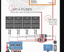
I don't have the understanding needed to explain the ground fault requirements, and personally I still see benefit in fusing both legs. However, the one requirement from 2017 NEC that is easier to understand is that there needs to be a disconnect between the solar array output and the charge controller equipment that disconnects both legs. So in the end, this is a diagram of what you are looking at.
View attachment 109437
At any rate, we want you to be both safe and successful. Have fun!


")