hwy17
Anti-Solar Enthusiast
This is a Schneider MPPT 100 600 standalone charge controller. I use an XW+ inverter as well.So what inverter is this?
This is a Schneider MPPT 100 600 standalone charge controller. I use an XW+ inverter as well.So what inverter is this?
See post #7!So what inverter is this?
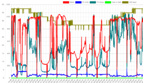
Yup you got it exactly! There are some plots on another thread of mine illustrating this hereI don't understand this effect in MPPT mode where my power point seems to start off high, 400v, early in the morning, gets into .7-1kW output still on the high side at 350v, and then actually dips mid morning, running 270-290v at 1.5kW now, before it will come back up into 330-350v in the main curve of 2-3.5kW production.
No doubt there's a perfectly reasonable explanation for that in the dynamics of PV output. I just don't have my head wrapped around it.
Edit: Ohhh, this is probably that shading I mentioned earlier that goes away by 11. It's a shading effect, and what you were getting at about how a fixed voltage would specifically not handle shading well.
Might as well take the detour here on that while we're at it:Well by the sounds of it you really are going to rely on that fuse for fire protection so I hope you take into account the mounting and cooling of that cable in calculating it's hoped for ampacity!
Existing is on the end of the same 250ft wire that the second array would be added onto.In your specific case the new string would be connected by a cable having a loop resistance of an Ohm, quite large but you don't say what the existing array is connected by
It's still not out of the question for me.Trying to control cable current by setting a fixed voltage is a non-starter as your system will no longer operate during shading.
Yup, np, it's an idea that will get its own thread to report the results if I ever actually get to trying it.So fuse your cable above Impp and leave the inverter in mpp mode rather than fixed voltage is my advice. I think further discussion of this should be in a new thread.
It's my own design and it is rather customized in that it is directly connected to a water tank heater that always gets priority any surplus being sent to the grid with export strictly controlled (as I don't get paid for it). The software is entirely assembly language for speed running on a PIC24EP at 40Mips, it is a transformer coupled full-bridge with primary side modulation (just to be different). THD is very low & EMC almost non-existent!So what is your hardware like anyway? With the custom tracking logic I would've guessed something home made, but you also refer to it as an inverter. Is this advanced programming control of an off the shelf AIO?
I guess the long averaging period has to be weighed up against changing illuminanceWhat I chose to do was to implement thermal current limiting by averaging input current over a minute and forcing mppt to increase voltage a step if the limit were exceed (increasing voltage will reduce current) until such time as the average current subsides.
Yup just like here in Lincolnshire, I wanted to absorb those peaks without chopping them off by interfering with MPPT straight away and in many cases the average is nowhere near any sensible limit hence the thermal limiting by averaging over a long period as what I am really trying to do is protect PCB traces & the PV current sense resistor. It all came about when adding a second parallel string as Impp/sc suddenly became twice the original design criteria, fortunately I tend to build with slack in hand but it still needed something to protect critical paths in worst case scenario's of MPPT going off on a bender! (software even written by oneself remains unpredictable at times IMOP lols).I guess the long averaging period has to be weighed up against changing illuminanceWe seem to have so many sporadic clouds in East Anglia recently my power output is up and down like a yo-yo.

When I was a teenager and I thought about learning some programming, I wanted to start with assembly, because it seemed there was no point in learning on top of a bunch of abstractions. I didn't get anywhere lol.It's my own design and it is rather customized in that it is directly connected to a water tank heater that always gets priority any surplus being sent to the grid with export strictly controlled (as I don't get paid for it). The software is entirely assembly language for speed running on a PIC24EP at 40Mips, it is a transformer coupled full-bridge with primary side modulation (just to be different). THD is very low & EMC almost non-existent!


Awesome stuff. I got into building some 12v relay logic off my BMS with chassis mounted relays and it clicked to me how the story of circuitry is all about shrinking them. My chassis mounted relay bank is already growing out of my box. I would like to get into the scale of that kind of board next. Something I can wire bits into by hand but use board mounted components.Abstraction is ok if you don't need exact timing and total control of the hardware! When you have self-destructing hardware with high energies around it's a bit better to have cast iron control of what's going on or BANGusually expensive!!
Ohh I wouldn't countenance anything containing large amounts of Lithium anywhere near me
IMOP unless your going fully off grid storage is not worth the hassle or investment.
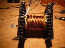
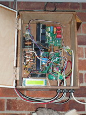
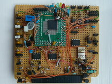
Here are some pic's please excuse my prototyping........
View attachment 214069View attachment 214070View attachment 214071
Ah! Proper electronics where you can see the components without an electron microscopeHere are some pic's please excuse my prototyping........
View attachment 214071
Have to agree there.Abstraction is ok if you don't need exact timing and total control of the hardware! When you have self-destructing hardware with high energies around it's a bit better to have cast iron control of what's going on or BANGusually expensive!!
Well actually the purpose of the second string is to cover a different part of the sky to deliberately extend the solar day or mitigate some of the local shading effects however during the overlap period on an ideal day they can both be capable generating maximum current hence the problem.I guess the mppt is operating outside it's design parameters, hence the interesting behavior. In a perfect world, one might have both parallel strings in matching azimuth/inclination.


