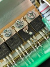
The picture shows the battery side H-bridge MOSFET's. There will be four separate groups of paralleled MOSFET's to make the H-bridge to drive the ferrite transformer step up transformer. These MOSFET's are on the PCB edge heat sink. They blew out due to battery to HV DC converter overload.
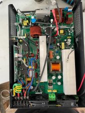
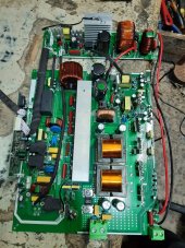
The PV input goes to a boost DC-DC converter (separate PCB at top of your picture) and is injected to high voltage DC point in inverter. The PV inputs are obviously not isolated from HV DC section so you momentarily shorted out the HV DC source internal to inverter.
Besides overloading battery to HV DC converter, you may have blown out IGBT devices in the middle heatsink. There are 4 devices at bottom of middle heat sink that are synchronous rectifiers for battery to HV DC converter and 4 devices at top of middle heat sink which is the Sinewave PWM chopper to converter HV DC to sinewave. The big toroid inductor at end of middle heat sink is PWM-sinewave filter inductor. In the middle of this heatsink there is likely one extra IGBT and a TO220 diode for HV DC to battery DC-DC buck converter to charge battery from HV DC supply.
Check the IGBT's for collector to emitter shorts. Sometimes the low value resistors in series with the IGBT gate drive also goes open, and sometimes the gate drivers gets blown out.
You should also check to see if the PV SSC PCB IGBT and diode on separate PCB got damaged.
View attachment 90523
View attachment 90533